A water drone with folding function
A technology of drones and functions, applied in the field of drones, can solve the problems of lack of automatic folding protection of wings
- Summary
- Abstract
- Description
- Claims
- Application Information
AI Technical Summary
Problems solved by technology
Method used
Image
Examples
Embodiment 1
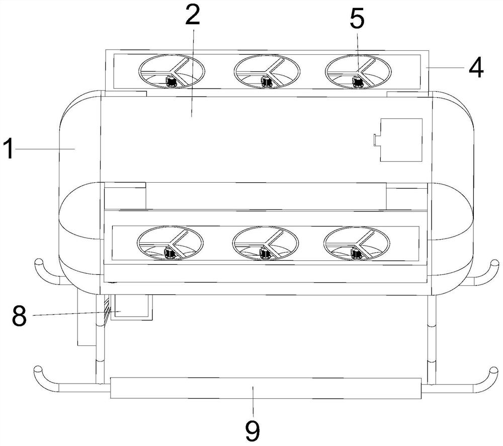
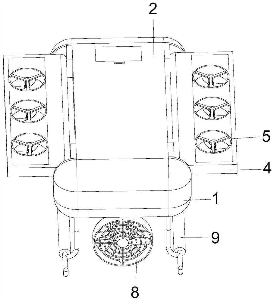
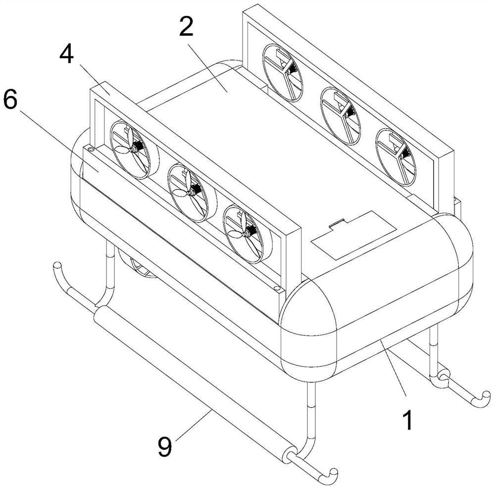
[0032]Please refer to Figures 1-5, a water drone with folding function, including a body 1, the body 1 is arranged in a rectangular structure with a hollow inside, the top of the body 1 is connected to the outside, the top of the body 1 is provided with a cover 2, and the body 1 The top is provided with two rotating shafts 3 in a front and rear symmetrical structure. A support frame 4 is fixed on the outer side of the rotating shaft 3. The support frame 4 is arranged in a hollow interior structure. The supporting frame 4 is provided with a lifting assembly 5. Both ends extend to the interior of the body 1, the interior of the left end of the body 1 is provided with a wing assembly 6 relative to the position between the two rotating shafts 3, the position of the middle of the body 1 is provided with a drive assembly 7, and the position of the bottom of the left end of the body 1 is provided with sliding Component 8, the bottom end of the body 1 is provided with two legs 9 in a f...
Embodiment 2
[0036] Referring to FIG. 6, the difference in combination with the basis of Embodiment 1 is that the wing-retracting assembly 6 includes a support plate 601, the support plate 601 is located in the middle of the left end of the body 1, and a motor B602 is fixed on the top surface of the support plate 601. The end of the output shaft of the motor B602 is sleeved with a bevel gear A603, the position between the left ends of the two rotating shafts 3 is a rotating rod A604, and the outer wall of the rotating rod A604 is sleeved relative to the rotating shaft 3 and the position of the motor B602 is sleeved with a bevel gear B605. 3. Bevel gear C606 is sleeved on the outer wall of the left end. Bevel gear B605 is vertically meshed with bevel gear A603 and bevel gear C606 respectively. There are rotating rods B607 vertically under the front and rear ends of rotating rod A604. The bottom end of rotating rod B607 extends to body 1 internal and rotationally connected to it.
[0037] Th...
Embodiment 3
[0041] Referring to FIG. 7, the difference between the foundations of Embodiments 1 and 2 is that the sliding assembly 8 includes a support rod 801, the support rod 801 is fixed on the bottom surface of the right end of the body 1, and the support rod 801 is arranged in a hollow cylindrical structure. The support rod 801 is internally provided with a connecting rod 802 rotatably connected with it, the bottom end of the connecting rod 802 extends through the bottom surface of the body 1 to the bottom, a sealing box 803 is fixed at the bottom end of the connecting rod 802, and the top end of the connecting rod 802 passes through the support rod 801 The top surface extends above it, a worm wheel 804 is sleeved on the outer wall of the top end of the connecting rod 802 , and a worm wheel 805 is provided on the top surface of the support rod 801 relative to the front side of the worm wheel 804 .
[0042] The sliding assembly 8 also includes a rotating rod C806. The rotating rod C806...
PUM
 Abstract
Description
Claims
Application Information
 - R&D
- Intellectual Property
- Life Sciences
- Materials
- Tech Scout
- Unparalleled Data Quality
- Higher Quality Content
- 60% Fewer Hallucinations
Browse by: Latest US Patents, China's latest patents, Technical Efficacy Thesaurus, Application Domain, Technology Topic, Popular Technical Reports.
© 2025 PatSnap. All rights reserved.Legal|Privacy policy|Modern Slavery Act Transparency Statement|Sitemap|About US| Contact US: help@patsnap.com


