Decorative plate mounting system

A technology for installation systems and decorative panels, applied in covering/lining, construction, building structure, etc., can solve the problems of large surface spacing, time-consuming and laborious nailing, occupation, etc., to reduce installation spacing, save man-hours and labor. Effect

Pending Publication Date: 2021-02-19
JIANGSU PIVOT NEW DECORATIVE MATERIALS
View PDF0 Cites 0 Cited by
  • Summary
  • Abstract
  • Description
  • Claims
  • Application Information

AI Technical Summary

Problems solved by technology

Generally, the installation of decorative panels on the wall is firstly leveled on the wall through square pipes or light steel. After leveling, the keel is laid on the wall. After the keel is laid, the decorative panel is installed, and the decorative panel is installed on the keel. It needs to be fixed with screws, which not only cannot ensure the accuracy of one-time installation and positioning, but also takes time and effort to nail on site, requiring high operating experience
Moreover, the distance between the finished surface from the raw wall to the decorative board is relatively large, which takes up a large space
In addition, the entire installation process is relatively traditional, which cannot keep up with the requirements of today's modular installation of decorative panels.

Method used


Image

  • Decorative plate mounting system
  • Decorative plate mounting system
  • Decorative plate mounting system

Examples


Embodiment 1

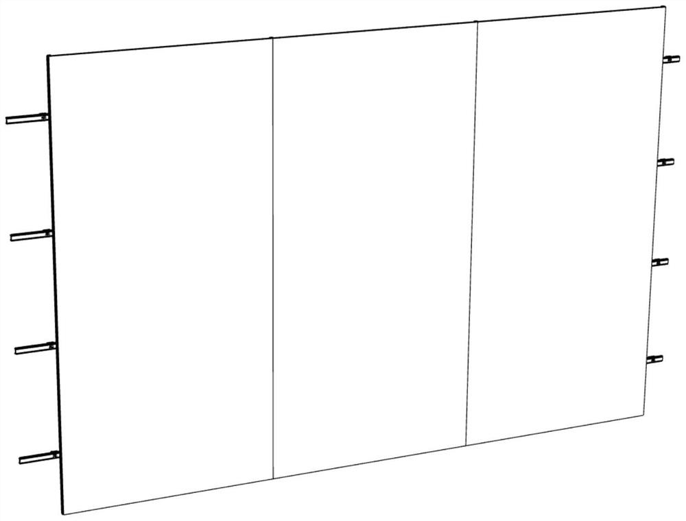
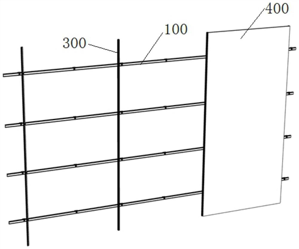
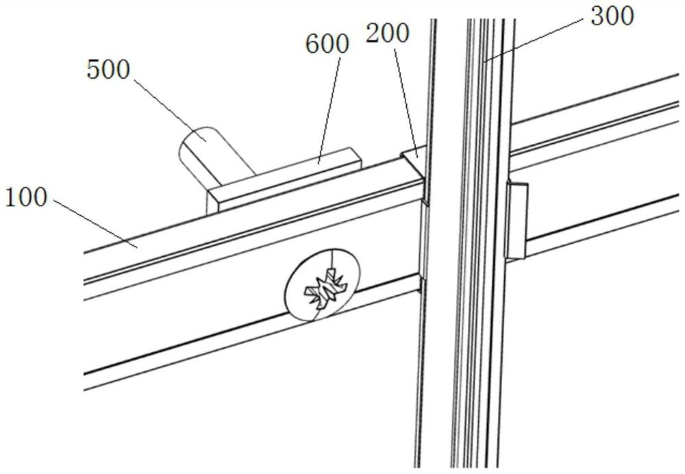
[0053] Embodiment 1, as figure 1 and figure 2 As shown, four keels 100 are arranged horizontally on the wall, four vertical clamping profiles 300 are arranged on the keels 100 , and three decorative panels 400 are arranged inside the clamping profiles 300 .

Embodiment 2

[0054] Embodiment 2, as Figure 12 As shown (decorative panels are not shown in the figure), the wall surface is divided into a first part and a second part arranged up and down, two keels 100 are arranged on the first part, and four vertical clamping profiles 300 are arranged on the two keels 100 , three decorative panels 400 are arranged in the clamping profiles 300, and two keels 100, four clamping profiles 300, and three decorative panels 400 are arranged in the second part as in the first part, in order to close the edges of the decorative panels 400, Six vertical keels 100 are provided at the three positions above the first part, below the second part and between the first part and the second part, and the six keels 100 at the three positions are all provided with transverse clamping profiles 300 , the upper and lower clamping profiles 300 are single-sided clamping profiles 301 , the middle clamping profile 300 is double-sided clamping profiles 302 , and the decorative p...


PUM


Abstract

The invention relates to a decorative plate mounting system. The decorative plate mounting system is characterized by comprising keels (100), clamping fasteners (200), clamping profiles (300) and a decorative plate (400), wherein rear clamping slots are formed in the back surfaces of the clamping fasteners; the rear blocking slots are used for clamping the clamping fasteners onto the keels; frontclamping slots are formed in front surfaces of the clamping fasteners for clamping the clamping profiles; the clamping profiles are used for clamping the decorative plate; and a crossed angle is formed between the rear clamping slots and the front clamping slots. The decorative plate mounting system disclosed by the invention saves working hours and labor power during decorative plate mounting construction, reduces a mounting spacing between the decorative plate and a wall surface, can accomplish integral mounting without other parts by only needing buckling operation after keels are mounted,and realizes modularized mounting.

Description

technical field [0001] The present invention relates to a decorative panel installation system. Background technique [0002] For the aesthetics of architectural decoration, decorative panels are generally installed on walls and become one of the current decoration methods. Generally, the installation of decorative panels on the wall is firstly leveled on the wall through square pipes or light steel. After leveling, the keel is laid on the wall. After the keel is laid, the decorative panel is installed, and the decorative panel is installed on the keel. When installing, it needs to be fixed with screws, which not only cannot ensure the accuracy of one-time installation and positioning, but also takes time and effort to nail on site, and requires high operating experience. Moreover, the finished surface distance from the raw wall to the decorative board is relatively large, which takes up a large space. In addition, the entire installation process is relatively traditional,...

Claims


Application Information

Patent Timeline
Patent Type & Authority Applications(China)
IPC IPC(8): E04F13/22E04F13/24
CPCE04F13/0805E04F13/081
Inventor 潘春军赵维王超向海林
Owner JIANGSU PIVOT NEW DECORATIVE MATERIALS
Why Eureka
Try Eureka