A pipeline protection device

A technology for pipes and protective structures, applied in the direction of pipe components, pipes/pipe joints/pipes, mechanical equipment, etc., can solve the problems of extra consumption of production factors, poor practicability, and production impact, etc., to ensure safe and stable operation, reduce Cost and effect of increasing outflow efficiency

Active Publication Date: 2021-06-22
青海亚洲硅业硅材料有限公司
View PDF0 Cites 0 Cited by
  • Summary
  • Abstract
  • Description
  • Claims
  • Application Information

AI Technical Summary

Problems solved by technology

At present, the conventional avoidance method is to inspect the thickness of the pipeline, and replace the pipeline in time when defects are found. This method is not practical because it needs to purchase testing equipment or entrust an external unit to do the inspection, and the replacement of the pipeline requires the system to stop or the corresponding pipeline to be disconnected. Not only will it affect production, but it will also cause additional consumption of various production factors and increase costs

Method used


Image

  • A pipeline protection device
  • A pipeline protection device
  • A pipeline protection device

Examples


Embodiment

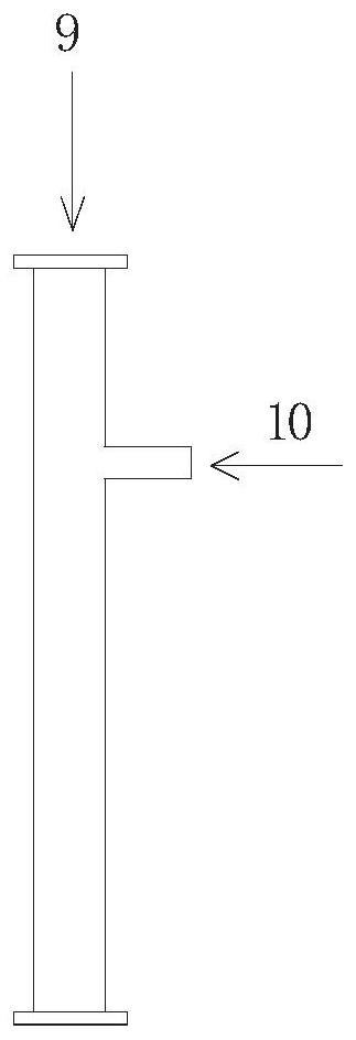
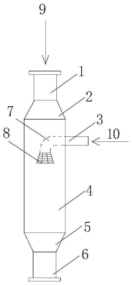
[0036] refer to figure 2 As shown, a pipeline protection device provided by an embodiment of the present invention includes a low-temperature fluid pipeline and a high-temperature fluid pipeline 3, and the low-temperature fluid pipeline and the high-temperature fluid pipeline are intersected and communicated with each other; the fluid output port of the high-temperature fluid pipeline 3 is located at The direction in which the high-temperature fluid 10 is output from the fluid output port of the high-temperature fluid pipeline to the low-temperature fluid pipeline is parallel to the flow direction of the low-temperature fluid 9 in the low-temperature fluid pipeline.

[0037] In this embodiment, the cryogenic fluid pipeline includes a first pipeline section 1 , a first concentric pipeline section 2 with different diameters, a third pipeline section 4 , and a second concentric pipeline section 5 with different diameters arranged coaxially and connected sequentially along a set d...


PUM


Abstract

The invention discloses a pipeline protection device, comprising a low-temperature fluid pipeline and a high-temperature fluid pipeline, the low-temperature fluid pipeline intersects with the high-temperature fluid pipeline and communicates with each other; the fluid output port of the high-temperature fluid pipeline is arranged in the low-temperature fluid pipeline, And the direction in which the high-temperature fluid is output from the fluid output port of the high-temperature fluid pipeline into the low-temperature fluid pipeline is parallel to the flow direction of the low-temperature fluid in the low-temperature fluid pipeline. The pipeline protection device provided by the invention reduces the vibration amplitude of the pipeline, avoids the damage caused by material cavitation and high pressure and high flow rate to the pipeline wall, reduces costs, and ensures safe and stable production operation.

Description

technical field [0001] The invention belongs to the technical field of pipeline protection, and in particular relates to a pipeline protection device. Background technique [0002] Whether it is in the field of life or petrochemical production, the pipeline is a very common device used to transport various media, such as gas, liquid or fluid with solid particles. Due to the needs of the production process, such as figure 1 As shown, there is a T-shaped pipeline in which the low-temperature fluid 9 and the high-temperature fluid 10 converge in one pipeline. The erosion phenomenon makes the local pipe wall thickness thinner, and leakage will occur over time, and it will also cause pipeline vibration. At present, the conventional avoidance method is to inspect the thickness of the pipeline, and replace the pipeline in time when defects are found. This method is not practical because it needs to purchase testing equipment or entrust an external unit to do the inspection, and t...

Claims


Application Information

Patent Timeline
Patent Type & Authority Patents(China)
IPC IPC(8): F16L55/027F16L55/045
CPCF16L55/027F16L55/045
Inventor 李彦张婧卢生栋李晓虎叶发萍刘廷泽
Owner 青海亚洲硅业硅材料有限公司
Why Eureka
Try Eureka