Lens design method and system and line lamp lens

A design method and lens technology, applied in the field of lighting, can solve problems such as narrow application range and inability to accurately distribute light, and achieve the effect of improving the divergence angle

Active Publication Date: 2021-02-19
浙江光锥科技有限公司
View PDF13 Cites 2 Cited by
  • Summary
  • Abstract
  • Description
  • Claims
  • Application Information

AI Technical Summary

Problems solved by technology

[0004] The divergence angle of a conventional TIR lens is within 10°, and the patent with the publication number CN206572440U discloses a LED free-form surface lens based on total internal reflection. The divergence angle of the light, but the patent only discloses a free-form surface lens structure with a light divergence angle of 60°, and it cannot precisely distribute light for a specific angle, and the scope of application is narrow

Method used


Image

  • Lens design method and system and line lamp lens
  • Lens design method and system and line lamp lens
  • Lens design method and system and line lamp lens

Examples


Embodiment 1

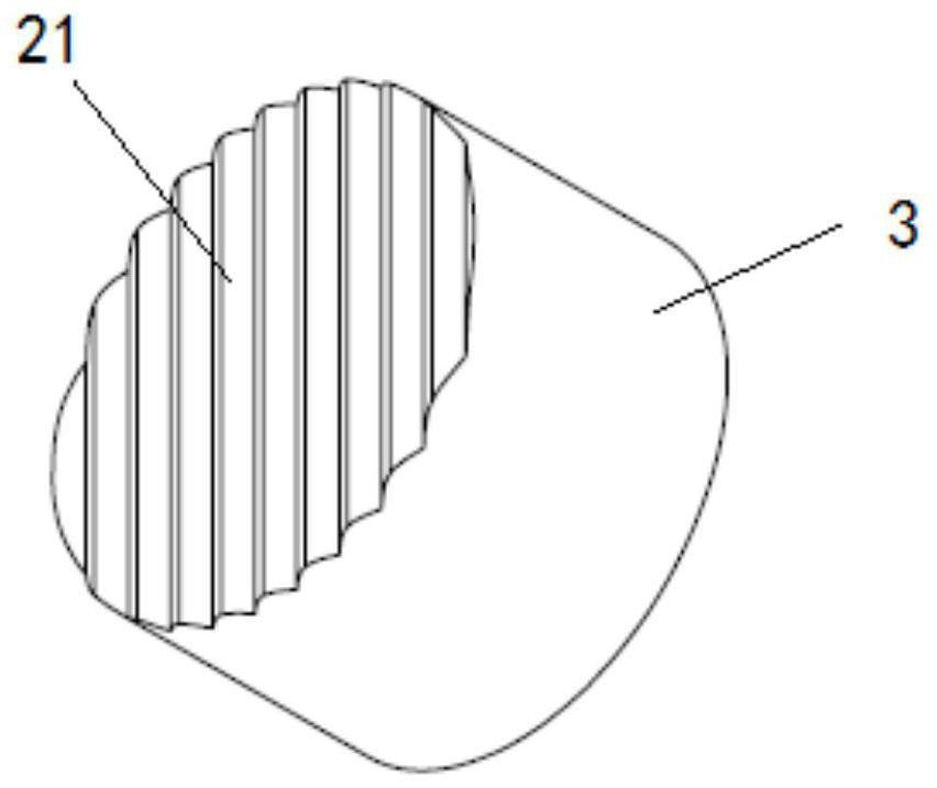
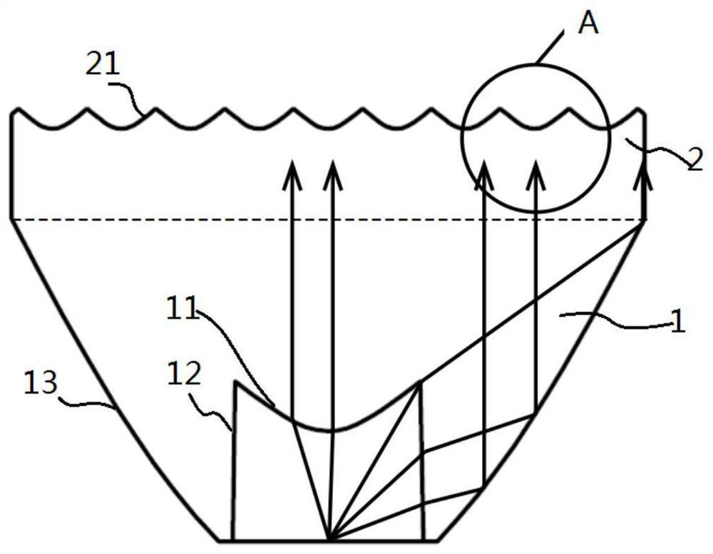
[0062] Embodiment 1, a kind of lens, such as Figures 1 to 4 As shown, the lens includes a lens body and a housing 3 with an inner cavity, wherein the lens body includes a collimated TIR structure 1 and an output layer 2, the collimated TIR structure 1 and the output layer 2 are located in the inner cavity, and the output layer 2 is located in Collimate the top of the TIR structure 1.

[0063] Such as image 3 As shown, the center of the light-emitting surface of the light source is located in the middle of the bottom of the lens, and the collimated TIR structure 1 is used to convert the light source light into collimated parallel light and emit it to the outgoing layer 2; the upper surface of the outgoing layer 2 is composed of several parallel The fringe curved surface 21 formed by the set fringes is the outgoing surface of the lens.

[0064] The striped curved surface 21 is a symmetrical structure, and the central point of the striped curved surface 21 is the highest poin...

Embodiment 2

[0153] Embodiment 2, when the initial refraction point is the vertex, after generating the corresponding striped surface 21 based on the section curve, a size optimization step is also included:

[0154] The height data also includes the thickness of the outgoing layer 2;

[0155] calculating and obtaining the height of the stripes based on the coordinates of each refraction point;

[0156] When the height of the stripes is smaller than the thickness of the emitting layer 2 , the height of the stripes is taken as the thickness of the emitting layer 2 .

[0157] When the applicable scene has relatively strict requirements on the size, the initial refraction point is used as the vertex, and the corresponding fringe surface 21 is generated with reference to the embodiment. At this time, the highest point of the fringe surface 21 is the preset lens height, and the lowest point of the fringe surface is not lower than the upper surface of the collimated TIR structure 1 .

[0158] ...

Embodiment 3

[0159] Embodiment 3. A lens design system, comprising:

[0160] The configuration module is used to configure the light distribution angle and initial size data, wherein the light distribution angle is greater than 0 and less than 90°, and the initial size data includes the height data of the lens and the width data of the stripes;

[0161] A design module, which includes a configuration unit, a coordinate calculation unit and a curve generation unit;

[0162] The configuration unit is configured to configure the number of refraction points on the section curve, generate incident light data corresponding to each refraction point based on the width data, and generate outgoing light corresponding to each refraction point based on the light distribution angle data;

[0163] The coordinate calculation unit is configured to use the apex or the lowest point of the stripe as an initial refraction point, determine the coordinates of the initial refraction point based on the height da...


PUM


Abstract

The invention discloses a lens design method and system and line lamp lens.An exit surface of the lens is a stripe curved surface formed by a plurality of stripes arranged in parallel, the design method comprises a method for designing section curves of the stripes, and the method comprises the following steps: configuring a light distribution angle and initial size data, wherein the initial sizedata comprises height data of the lens and width data of the stripes; configuring the number of refraction points on the section curve, generating incident light data corresponding to each refractionpoint based on the width data, and generating emergent light data corresponding to each refraction point based on the light distribution angle; taking the vertex or the lowest point of each stripe asan initial refraction point, determining the coordinate of the initial refraction point based on the height data, and calculating the refraction point coordinate of each refraction point in sequence based on the coordinate of the initial refraction point, the incident light data and the emergent light data; and generating a cross-section curve of the stripes based on the coordinates of the refraction points. According to the lens design method, the corresponding stripe curved surface can be designed based on the specified light distribution angle.

Description

technical field [0001] The invention relates to the field of lighting technology, in particular to a lens design method and system, and a line lamp lens. Background technique [0002] TIR, Total Internal Reflection, total internal reflection. [0003] Line lights are widely used in various buildings, indoor and outdoor local or contour lighting, such as building outlines and billboard production. Some application scenarios require line lights to have a small size and a large divergence angle. [0004] The divergence angle of a conventional TIR lens is within 10°, and the patent with the publication number CN206572440U discloses a LED free-form surface lens based on total internal reflection. The divergence angle of the light output, but the patent only discloses a free-form surface lens structure with a light output divergence angle of 60°, and it cannot precisely distribute light for a specific angle, and the scope of application is narrow. Contents of the invention [...

Claims


Application Information

Patent Timeline
Patent Type & Authority Applications(China)
IPC IPC(8): F21V5/04G02B27/00
CPCF21V5/04G02B27/0012
Inventor 泮璐媚仇旻樊军周键斌
Owner 浙江光锥科技有限公司
Why Eureka
Try Eureka