Engine piston connecting rod detection device

A technology of piston connecting rod and detecting device, which is applied to mechanical measuring devices, measuring devices, and mechanical devices, etc., can solve the problems of inaccurate, vertical, and incapable of guaranteeing vernier calipers and pistons in the detection method, so as to achieve better use effects and improved performance. The effect of precision

Inactive Publication Date: 2021-02-19
蒋笑成
View PDF0 Cites 0 Cited by
  • Summary
  • Abstract
  • Description
  • Claims
  • Application Information

AI Technical Summary

Problems solved by technology

[0003] At present, when the engine fails, the position of the engine piston is usually detected to determine whether the piston connecting rod is displaced and deformed. However, the existing detection method is usually to directly remove the spark plug and insert the vernier

Method used


Image

  • Engine piston connecting rod detection device
  • Engine piston connecting rod detection device
  • Engine piston connecting rod detection device

Examples


Embodiment 1

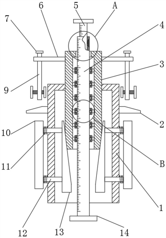
[0028] refer to Figure 1-4 , an engine piston connecting rod detection device, including a fixed cylinder 1, the top outer wall of the fixed cylinder 1 has a limit opening, and the inner wall of the limit opening is slidably connected with a movable cylinder 3, and the outer walls of the fixed cylinder 1 are all provided with sliding holes , and the inner wall of the sliding hole is slidably connected with a movable rod 12, one end of the movable rod 12 is fixedly connected with a movable block 13, and the other end of the movable rod 12 is fixedly connected with an arc-shaped plate 10, and one side of the movable block 13 is provided with an oblique Chamfering, the outer wall of the movable cylinder 3 has a circular chamfer, and the outer wall of the circular chamfer matches the outer wall of the oblique chamfer, the inside of the movable cylinder 3 is provided with a measuring mechanism, and the inside of the movable cylinder 3 is also provided with a As an auxiliary mechan...

Embodiment 2

[0036] refer to Figure 5 , a detection device for an engine piston and connecting rod. Compared with Embodiment 1, this embodiment further includes a rubber pad 25 bonded to the outer wall of the arc-shaped plate 10 .

[0037] Working principle: when in use, the rubber pad 25 on the arc-shaped plate 10 can increase the friction with the inner wall of the spark plug installation hole, making the fixing more stable.


PUM


Abstract

The invention discloses an engine piston connecting rod detection device which comprises a fixed cylinder, a limiting opening is formed in the outer wall of the top of the fixed cylinder, a movable cylinder is slidably connected to the inner wall of the limiting opening, sliding holes are formed in the outer walls of the periphery of the fixed cylinder, movable rods are slidably connected to the inner walls of the sliding holes, and a movable block is fixedly connected to one end of each movable rod; and an arc-shaped plate is fixedly connected to the other end of the movable rod, an inclinedchamfer is formed in one side edge of the movable block, a circular chamfer is formed in the outer wall of the movable cylinder, the outer wall of the circular chamfer is matched with the outer wall of the inclined chamfer, a measuring mechanism is arranged in the movable cylinder, and an auxiliary mechanism is further arranged in the movable cylinder. According to the invention, the fixed cylinder can be fixed in the mounting holes with different inner diameters, engines with different models can be detected, detection is more flexible, the fixing mode can ensure that the measuring rod is vertical to the piston, and the detection accuracy is effectively improved.

Description

technical field [0001] The invention relates to the technical field of engine detection, in particular to an engine piston connecting rod detection device. Background technique [0002] An engine is a machine that can convert other forms of energy into mechanical energy. It was first born in the UK. It is not only suitable for power generation devices, but also refers to the entire machine including power devices. Its types include internal combustion engines, external combustion engines, and electric motors. Wait. [0003] At present, when the engine fails, the position of the engine piston is usually detected to determine whether the piston connecting rod is displaced and deformed. However, the existing detection method is usually to directly remove the spark plug and insert the vernier caliper into the mounting hole. Since the vernier caliper cannot be guaranteed to be completely perpendicular to the piston, this detection method is very inaccurate. Therefore, it is urge...

Claims


Application Information

Patent Timeline
IPC IPC(8): G01B5/00G01B5/30G01B3/08
CPCG01B3/08G01B5/003G01B5/30
Inventor 蒋笑成
Owner 蒋笑成
Why Eureka
Try Eureka