FPGA-based speed filter algorithm

A filter and filter bank technology, applied in the direction of instruments, radio wave measurement systems, etc., can solve the problems of high cost, small space, high resource requirements, etc., to reduce resource consumption, save multiplier resources, and easy to implement Effect

Pending Publication Date: 2021-02-19
西安乾景防务技术有限公司
View PDF0 Cites 0 Cited by
  • Summary
  • Abstract
  • Description
  • Claims
  • Application Information

AI Technical Summary

Problems solved by technology

Although the weighting coefficient of the FIR filter can be used to increase the clock rate to achieve filter multiplexing, modern radar systems often use chirp signals with large time-width-bandwidth products, so that there is little room for increasing the FPGA processing clock speed
Although FIR filters bring convenience, they have high resource requirements and are difficult or costly to implement

Method used


Image

  • FPGA-based speed filter algorithm
  • FPGA-based speed filter algorithm
  • FPGA-based speed filter algorithm

Examples


Embodiment

[0034] The speed filter algorithm based on FPGA that the present embodiment provides, comprises the following steps:

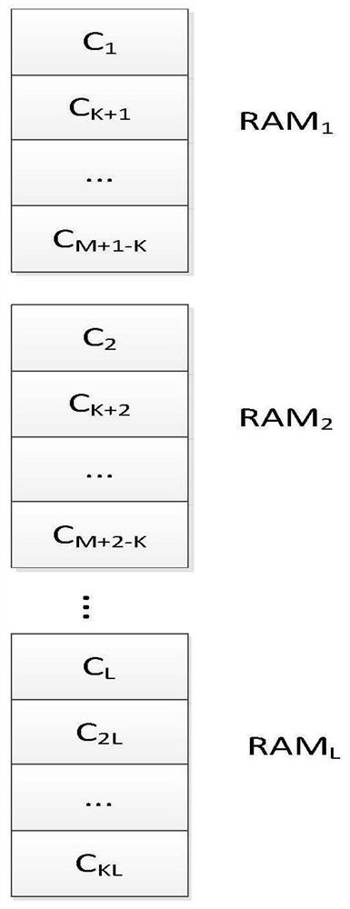
[0035] 1) When the system is initialized, the filter bank coefficients applicable to the current application scenario are bound to the on-chip RAM of the FPGA. Assuming that there are M speed units and the times of multiplexing in time is K, then M / K filter banks are required, and each filter bank is responsible for K sets of filter coefficients.

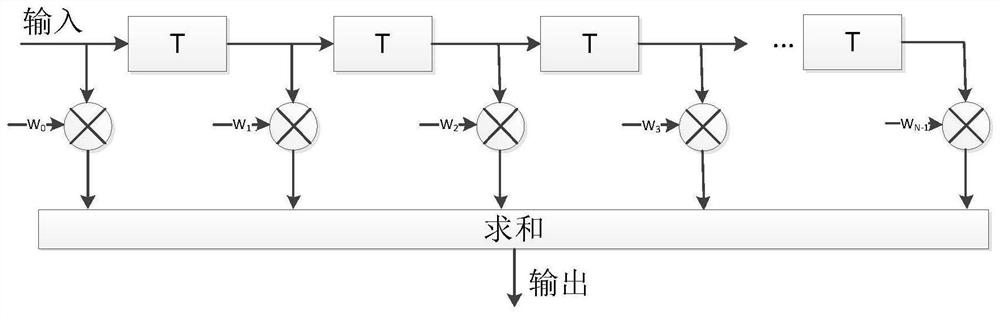
[0036] Such as figure 2 As shown in, RAM1 contains K sets of filter coefficients, and C1 contains A total of N coefficients correspond to an N-order filter.

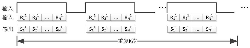
[0037] 2) After the radar echo data has undergone pulse compression, it is necessary to store the data of a pulse group first, trigger the read operation when the storage is completed, read the data according to a certain address rule, and put the same distance units of different pulses together, which is convenient for follow-up speed filter.

[0038] s...


PUM


Abstract

The invention belongs to the technical field of radar signal processing, and relates to an FPGA-based speed filter algorithm which comprises the following steps: 1) binding a filter bank coefficient on an on-chip RAM of an FPGA; 2) after the radar echo data is subjected to pulse compression, storing the data of the pulse group, triggering a reading operation after the storage is completed, readingthe data according to a certain address rule, and placing the same distance units of different pulses together; and 3) while reading the radar echo data, sequentially reading the filter bank coefficients stored in the RAM, correspondingly multiplying the filter bank coefficients, accumulating the multiplied results, completing the filtering of one speed unit after accumulating N pulses, and finally obtaining the filtering results of M speed units to complete the speed filtering function. According to the invention, the filter coefficients can be flexibly bound, and the filter order is not limited; while the advantages of the FIR filter bank are achieved, the resource requirement can be reduced, implementation is easy, and the cost is low.

Description

technical field [0001] The invention belongs to the technical field of radar signal processing and relates to an FPGA-based velocity filter algorithm. Background technique [0002] With the continuous development of radar technology, coherent pulse trains with different pulse repetition frequencies are used to extract the Doppler information of the target, and then to find the target. Such radar is Pulse Doppler (PD) radar. It has received extensive attention due to its wave suppression ability and range-velocity resolution. In recent years, with the rapid development of integrated circuits, the sampling rate of signals has been continuously improved; the multi-rate filter (FPGA) has the advantages of reducing transmission rate, reducing computational complexity, and reducing storage capacity. Multi-rate signal processing has been widely used. Applications. [0003] Moving target detection technology is a technology for extracting moving target information in PD radar sign...

Claims


Application Information

Patent Timeline
Patent Type & Authority Applications(China)
IPC IPC(8): G01S7/41
CPCG01S7/41
Inventor 冯璟徐卫丰
Owner 西安乾景防务技术有限公司
Why Eureka
Try Eureka