Resolver feedback signal frequency division method and system based on ad2s1210 resolver decoder chip
A AD2S1210, resolver decoding technology, applied in the direction of control system, general control system, vector control system, etc., can solve the problem of non-orthogonal pulse signal frequency division and other problems
- Summary
- Abstract
- Description
- Claims
- Application Information
AI Technical Summary
Problems solved by technology
Method used
Image

Examples
Embodiment 1
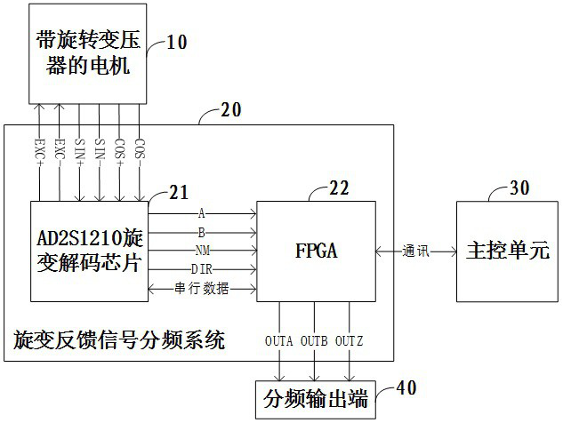
[0050] Please refer to figure 1 , is a schematic diagram of the structure and connection of a resolver feedback signal frequency division system in an embodiment, including a motor 10 with a resolver, a resolver feedback signal frequency division system 20 , a main control unit 30 and a frequency division output terminal 40 . The resolver feedback signal frequency division system 20 is used for decoding the resolver signal. The resolver feedback signal frequency division system 20 includes an FPGA22 and an AD2S1210 resolver decoding chip 21. The main control unit and the FPGA22 write address and data pairs through serial communication. AD2S1210 resolver decoding chip 21 is configured. The AD2S1210 resolver decoding chip 21 generates EXC+ / EXC- signals and sends them to the motor 10 with the resolver, and receives the SIN / COS signal fed back by the motor 10 with the resolver. According to the configuration information sent by the main control unit 30, the AD2S1210 resolver deco...
Embodiment 2
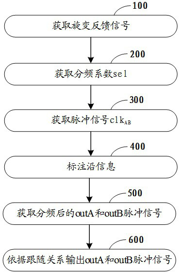
[0055] Please refer to figure 2 , is a schematic flowchart of a method for dividing the frequency of a resolver feedback signal in another embodiment, and the method for dividing the frequency of a resolver feedback signal includes:
[0056] Step 100: Obtain a resolver feedback signal.
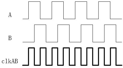
[0057] The resolver feedback signal is the A-phase pulse signal, B-phase pulse signal, NM-phase pulse signal and DIR direction signal output by the AD2S1210 resolver decoding chip according to a preset number of lines. Among them, the A-phase pulse signal and the B-phase pulse signal are mutually positive. The DIR direction signal is used to judge the following relationship between the A-phase pulse signal and the B-phase pulse signal. In one embodiment, the value of the preset number of lines is 16384.
[0058] Step 200, obtaining the frequency division coefficient sel.
[0059] The frequency division coefficient sel is the multiple of the frequency division of the resolver feedback signa...
PUM
 Abstract
Description
Claims
Application Information
 - R&D
- Intellectual Property
- Life Sciences
- Materials
- Tech Scout
- Unparalleled Data Quality
- Higher Quality Content
- 60% Fewer Hallucinations
Browse by: Latest US Patents, China's latest patents, Technical Efficacy Thesaurus, Application Domain, Technology Topic, Popular Technical Reports.
© 2025 PatSnap. All rights reserved.Legal|Privacy policy|Modern Slavery Act Transparency Statement|Sitemap|About US| Contact US: help@patsnap.com