Lighting energy-saving management system

A management system and lighting module technology, applied in the field of lighting systems, can solve problems such as the inability of lighting lamps to start according to demand, limited sensor information collection, and inability to intelligently switch, so as to avoid excessive power consumption, avoid excessive waste of power, and improve intelligence. control effect

Pending Publication Date: 2021-02-19
BEIJING ZIFENG HUANA TECH
View PDF0 Cites 0 Cited by
  • Summary
  • Abstract
  • Description
  • Claims
  • Application Information

AI Technical Summary

Problems solved by technology

[0003] At present, the lighting control system often used in office places often uses scattered sensors to directly control some lights, resulting in many positions. Once the lights are deployed in poor positions, some lights will not be able to perform as required due to the limited information collected by the sensors. Start-up, and secondly, in the process of daily use, there are many key positions that need to be turned on normally, but when it is not working, it needs to be turned off by personnel, which will easily cause waste of electric energy and cannot be carried out in accordance with the specified good working mode. Intelligent switching, followed by in the office, often the staff will turn on all the lights for excessive lighting, resulting in a waste of electric energy

Method used


Image

  • Lighting energy-saving management system
  • Lighting energy-saving management system
  • Lighting energy-saving management system

Examples


Embodiment Construction

[0035] The following will clearly and completely describe the technical solutions in the embodiments of the present invention with reference to the accompanying drawings in the embodiments of the present invention. Obviously, the described embodiments are only some, not all, embodiments of the present invention.

[0036] Examples of the described embodiments are shown in the drawings, wherein like or similar reference numerals designate like or similar elements or elements having the same or similar functions throughout. The embodiments described below by referring to the figures are exemplary and are intended to explain the present invention and should not be construed as limiting the present invention.

[0037] Below in conjunction with accompanying drawing and embodiment the present invention will be further described:

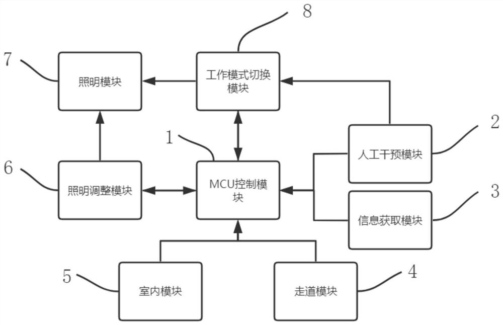
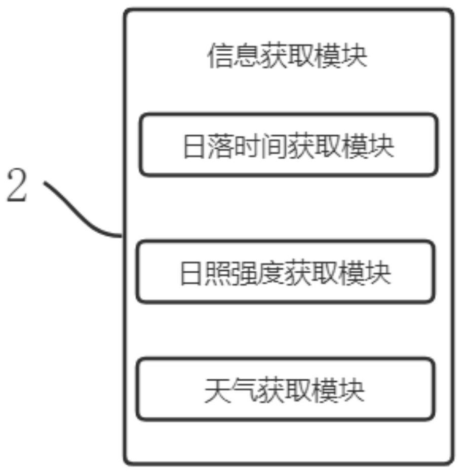
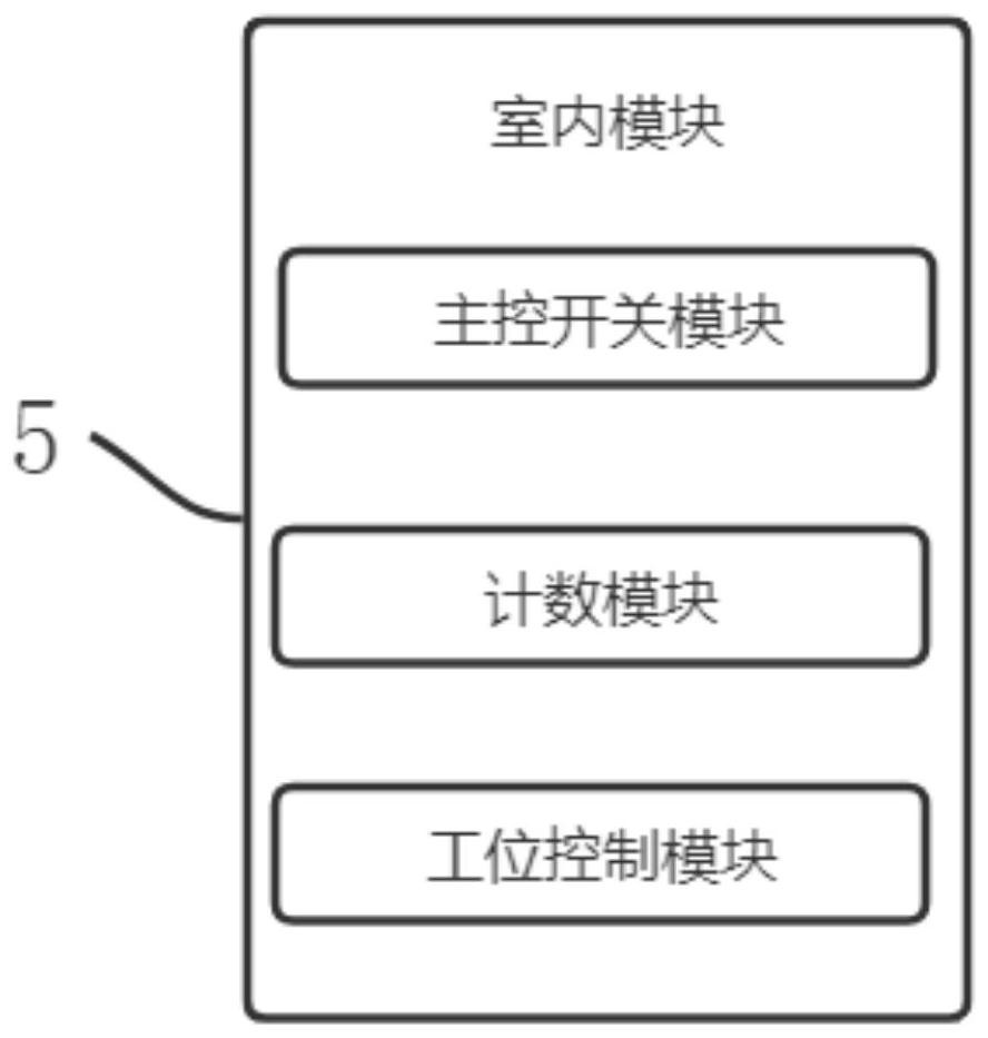
[0038] see Figure 1-6 , the present invention provides a technical solution: a lighting energy-saving management system, including: an MCU control module...


PUM


Abstract

The invention discloses a lighting energy-saving management system, and relates to the technical field of lighting systems. The lighting energy-saving management system comprises an MCU control modulefor processing, judging and storing data, a manual intervention module for adjusting and modifying the actual parameters, and an information acquisition module. According to the lighting energy-saving management system, through the information acquisition module and a photosensitive detection and calibration module, the comparison and calibration of data of lighting lamps at all positions can beachieved, the data acquisition and transmission accuracy of a sensor is further improved, and the situation that the lighting lamps cannot be turned on accurately due to poor accuracy of the sensor isavoided; through a working mode switching module, switching of preset working modes can be achieved; through presetting the working modes for rapid switching, intelligent control over the illuminating lamps is improved, and excessive electric energy waste of the illuminating lamps is avoided; through a station control module and a counting module, statistics of the number of workers can be achieved, and the illuminating lamps are normally opened for stations where people work.

Description

technical field [0001] The invention relates to the technical field of lighting systems, in particular to a lighting energy-saving management system. Background technique [0002] The lighting system is a system based on providing lighting, including natural lighting systems, artificial lighting systems and a combination of the two. It uses computers, wireless communication data transmission, computer intelligent information processing, spread spectrum power carrier communication technology and energy saving. The distributed wireless telemetry, remote control, and remote communication control system composed of technologies such as electric appliance control can realize the safety, energy saving, convenience, comfort, and artistry of lighting applications. [0003] At present, the lighting control system often used in office places often uses scattered sensors to directly control some lights, resulting in many positions. Once the lights are deployed in poor positions, some l...

Claims


Application Information

Patent Timeline
Patent Type & Authority Applications(China)
IPC IPC(8): H05B47/11H05B47/165H05B47/115H05B47/12
CPCH05B47/11H05B47/115H05B47/12H05B47/165Y02B20/40
Inventor 李健李霞李浩洋
Owner BEIJING ZIFENG HUANA TECH
Why Eureka
Try Eureka