
Filter for removing viruses

A filter and virus technology, applied in the field of virus-removing filters, can solve the problems of inconvenient processing and complex structure of the membrane support plate, and achieve the effects of simple assembly, increased virus retention, and easy manufacture

Pending Publication Date: 2021-02-23
HANGZHOU COBETTER FILTRATION EQUIP
View PDF13 Cites 6 Cited by
  • Summary
  • Abstract
  • Description
  • Claims
  • Application Information

AI Technical Summary

Problems solved by technology

[0005] The object to be achieved by the present invention is to provide a filter for removing viruses, so as to solve the problems of complex membrane support plate structure and inconvenient processing in the existing filter; in the filter, the membrane support plate has simple structure and convenient processing At the same time, the area of ​​the filter membrane sealed on both surfaces of the membrane support plate is larger to provide a larger filtration area and the fluid flow path is simpler

Method used


Image

  • Filter for removing viruses
  • Filter for removing viruses
  • Filter for removing viruses

Examples


Embodiment 1

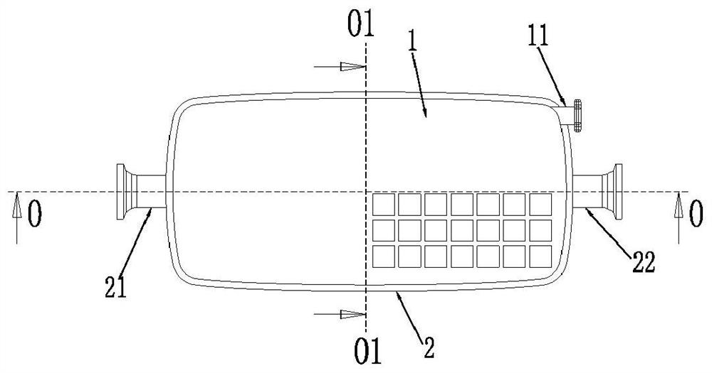
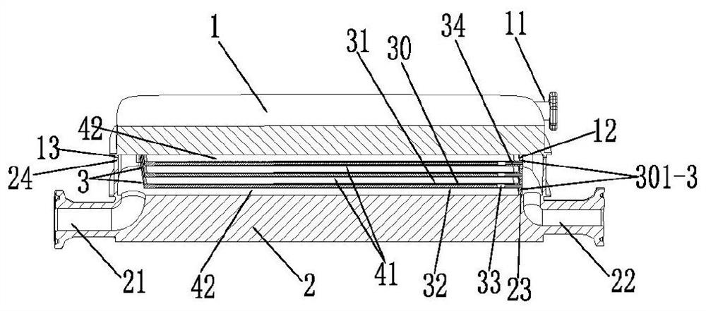
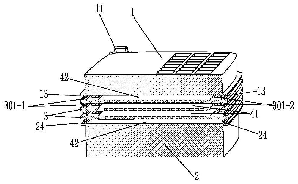
[0078] Such as Figure 1-Figure 6 The filter for removing viruses of the first structure shown includes a liquid inlet 21, a liquid outlet 22, an exhaust port 11, a top cover 1, a bottom cover 2 and a seal fixed on the top cover 1 and the bottom cover. The filter plate 3 between 2, the exhaust port 11 is located in the top cover 1. In this embodiment, both the liquid inlet 21 and the liquid outlet 22 are located in the bottom cover 2 . Of course, the liquid inlet 21 and the liquid outlet 22 can also be separately provided on the top cover 1 and the bottom cover 2 .

[0079] Such as figure 2 with image 3 As shown, the filter plate 3 includes a membrane support plate 30 and a first filter membrane 31 and a second filter membrane 32 that are respectively sealed and fixed on the first surface and the second surface of the membrane support plate 30, the first filter membrane 31 and the second filter membrane The membranes 32 each include multiple layers, and the outer surface...

Embodiment 2

[0110] Such as Figure 7-13 The virus-removing filter of the second structure shown is substantially the same structure as the filter provided in Example 1, and will not be repeated here. However, in this filter, the structure of the membrane support plate 30 is slightly different, which will be described in detail below.

[0111] Such as Figure 11-Figure 13 As shown, the main structure of the membrane support plate 30 is the same as the main structure of the membrane support plate 30 in Embodiment 1, the difference is: in this embodiment 2, the membrane support plate 30 has a first end close to the liquid inlet 21 and Near the second end of the liquid outlet 22, the first end of the membrane support plate 30 has a third through hole 30C communicated with the liquid inlet 21, and the second end of the membrane support plate 30 has a fourth through hole communicated with the liquid outlet 22. The through hole 30D, which is located at the outlet 304B end of the confluence cha...

Embodiment 3

[0119] In this embodiment, the main structure of the filter is the same as that of the filter provided in Embodiment 2. However, in the third embodiment, the structure of the membrane support plate 30 is different from that of the membrane support plate 30 in the second embodiment.

[0120] Such as Figure 18-Figure 20 As shown, only the first end of the membrane support plate 30 near the liquid inlet 21 is formed with a third through hole 30C penetrating through its entire thickness, and the fourth through hole 30D is not provided at its second end near the liquid outlet 22. . Of course, a fourth through hole 30D may also be provided.

[0121] The first surface of the film support plate 30 has a first through hole 30A, and the second surface has a second through hole 30B, and the first through hole 30A, the second through hole 30B and the outlet are formed between the first surface and the second surface. The confluence channel 304 communicated with the liquid port 22 .

...


PUM


Abstract

The invention relates to a filter for removing viruses. The filter comprises a liquid inlet, a liquid outlet, a top cover, a bottom cover and a filter plate hermetically fixed between the top cover and the bottom cover, wherein the filter plate comprises a membrane supporting plate, and a first filter membrane and a second filter membrane hermetically fixed on a first surface and a second surfaceof the membrane supporting plate respectively. A first through hole and a second through hole are formed in the first surface and the second surface of the membrane supporting plate respectively; a confluence channel is formed between the first surface and the second surface and communicates with the first through hole, the second through hole and the liquid outlet; and the first filter membrane and the second filter membrane cover the first through hole and the second through hole respectively. A feed fluid flows in from a liquid inlet and is filtered by the first filter membrane and the second filter membrane, and a clean filtrate flows into the confluence channel through the first through hole and the second through hole, finally flows to the liquid outlet and is discharged. In the filter, the membrane supporting plate is simple in structure, convenient to process and manufacture and easy to assemble and operate, and a larger filtering area and a simple fluid flow path can be provided.

Description

technical field [0001] The invention relates to the technical field of filtration, in particular to a filter for removing viruses. Background technique [0002] Chinese patent CN102065985B discloses a filter box body formed by stacking plates, which includes an inlet, an outlet, an exhaust port, a top cover box, a bottom cover box, and a plurality of filter units sealed and fixed between the two, each filter unit includes 2 filter plates, each filter plate has a membrane support plate, a first membrane and a second membrane, the membrane support plate has a top surface with relatively large internal dimensions and a bottom surface with relatively small internal dimensions, the first membrane is sealed To the top surface of the film support plate, the second film is sealed to the bottom surface of the film support plate, the size of the first film is larger than the size of the second film. On both sides of the film support plate, two groups of holes parallel to the length d...

Claims


Application Information

Patent Timeline
Patent Type & Authority Applications(China)
IPC IPC(8): B01D61/00
CPCB01D61/00
Inventor 贾建东郭江明徐燕辉
Owner HANGZHOU COBETTER FILTRATION EQUIP
Learn More