
Fixing clamp capable of overturning for industrial robot part maintenance

A technology of industrial robots and fixtures, which is applied in the field of tooling fixtures, can solve the problems of inability to flip parts, troubles, and reduce maintenance efficiency of maintenance personnel, so as to achieve the effects of easy maintenance, avoiding shaking, and improving maintenance efficiency

Inactive Publication Date: 2021-02-23
广州钦丰科技有限公司
View PDF0 Cites 1 Cited by
  • Summary
  • Abstract
  • Description
  • Claims
  • Application Information

AI Technical Summary

Problems solved by technology

[0005] Aiming at the deficiencies of the prior art, the present invention provides an overturnable fixing fixture for repairing parts of industrial robots, which can directly turn over the fixed parts by 180 degrees, so that maintenance personnel can easily perform maintenance on the other side of the parts. Maintenance, the advantage of improving the maintenance efficiency of maintenance personnel, solves the problem that the general maintenance jig cannot directly flip the parts after fixing the parts. It is necessary to loosen the jig first, then use other tools to flip the parts, and finally fix the repair again. Not only troublesome, but also a problem that reduces the maintenance efficiency of maintenance personnel

Method used


Image

  • Fixing clamp capable of overturning for industrial robot part maintenance
  • Fixing clamp capable of overturning for industrial robot part maintenance
  • Fixing clamp capable of overturning for industrial robot part maintenance

Examples


Embodiment Construction

[0025] The following will clearly and completely describe the technical solutions in the embodiments of the present invention with reference to the accompanying drawings in the embodiments of the present invention. Obviously, the described embodiments are only some, not all, embodiments of the present invention. Based on the embodiments of the present invention, all other embodiments obtained by persons of ordinary skill in the art without making creative efforts belong to the protection scope of the present invention.

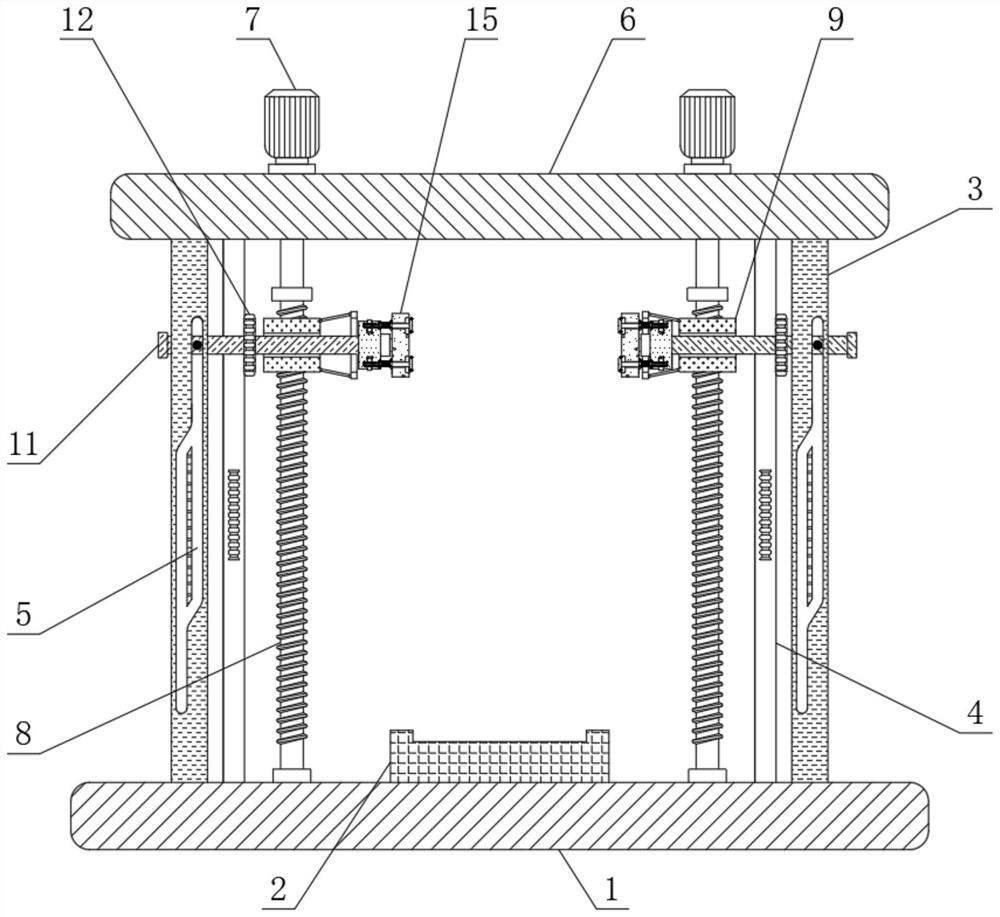
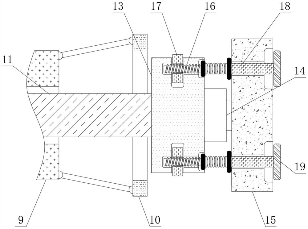
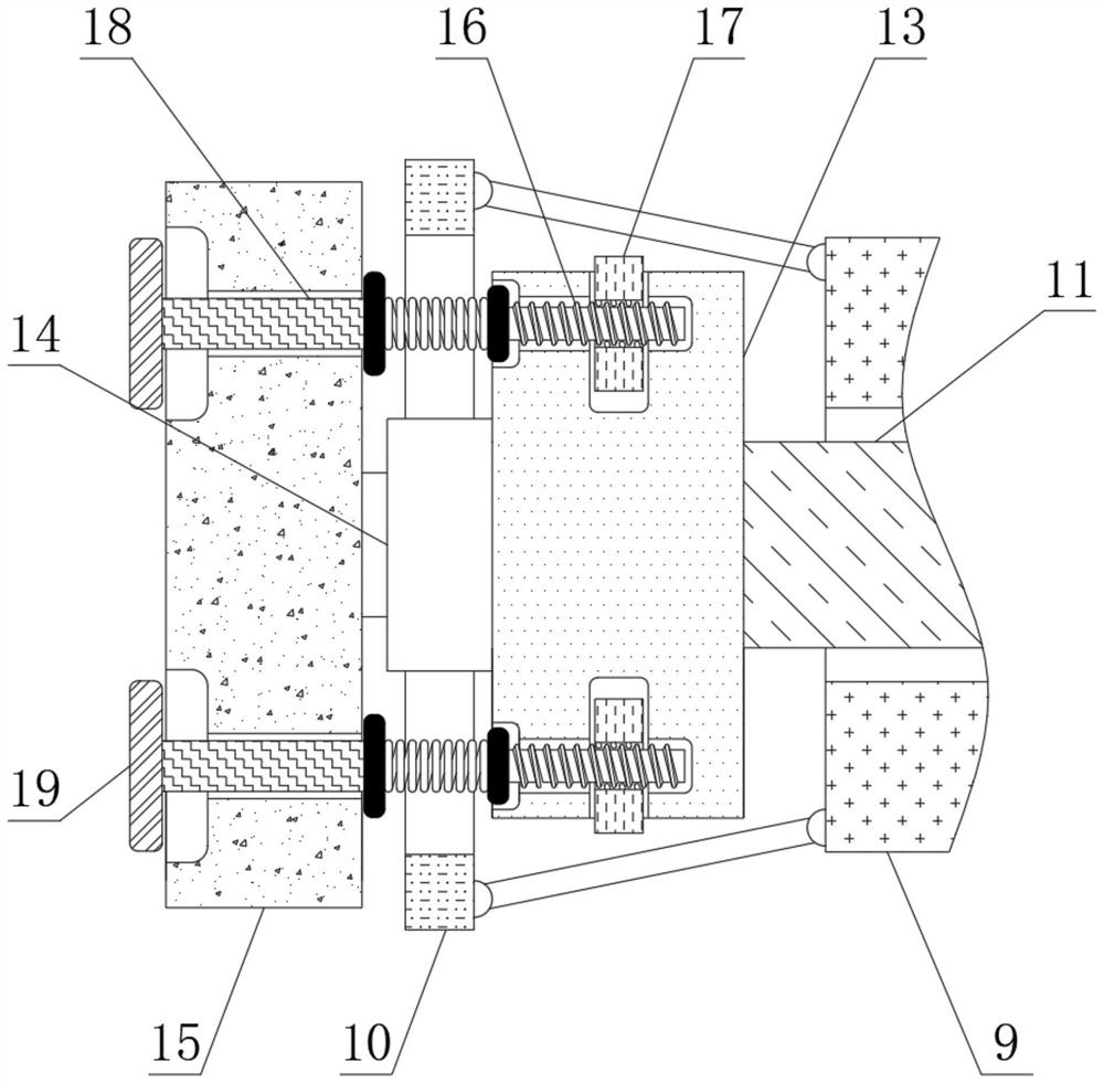
[0026] see Figure 1-5 , a kind of fixed fixture for the maintenance of industrial robot parts that can be turned over, includes a workbench 1, and the top of the workbench 1 is fixedly connected with a storage plate 2, two rail plates 3 and two support rods 4, and the two rail plates 3 Rail grooves 5 are opened on the front side, and the top of the rail plate 3 and the support rod 4 is fixedly connected with a horizontal plate 6, and the top of the horizontal...


PUM


Abstract

The invention relates to the technical field of tool clamps, and discloses a fixing clamp capable of overturning for industrial robot part maintenance. The fixing clamp comprises two sliding tables, the opposite sides of the two sliding tables are fixedly connected with gear rings correspondingly, movable shafts are connected to the interior of the two sliding tables in an inserted mode correspondingly, fixing blocks are fixedly connected to the opposite sides of the two movable shafts correspondingly, clamping plates are fixedly connected to the opposite sides of the two fixing blocks correspondingly, four second threaded rods are connected into the opposite sides of the two fixing blocks in an inserted mode correspondingly, the outer parts of the second threaded rods are sleeved with pinions correspondingly, four movable rods are connected into the opposite sides of the two clamping plates in an inserted mode correspondingly, and ejection plates are fixedly connected to the oppositesides of the movable rods correspondingly. When the sliding tables move upwards to enable the movable shafts and the fixed blocks to rotate, the pinions drive the second threaded rods to move in the direction of the clamping plates under the action of the gear rings, then the movable rods and the ejection plates are driven by a compression spring to prop against a maintenance part, and therefore the effect of preventing the maintenance part from sliding during overturning is achieved.

Description

technical field [0001] The invention relates to the technical field of tooling fixtures, in particular to a reversible fixing fixture for repairing parts of industrial robots. Background technique [0002] Industrial robots are multi-joint manipulators or multi-degree-of-freedom machine devices with a certain degree of automation. They can rely on their own power sources and control capabilities to achieve various industrial processing and manufacturing functions. Industrial robots are widely used in electronics, logistics, and chemical industries. in the industrial field. [0003] After the industrial robot is used for a long time, the parts are prone to damage and need to be repaired. When repairing the robot parts, it is necessary to use the tooling fixture to fix the robot parts and then repair them. After the parts are fixed by the general maintenance fixture, the parts cannot be fixed Flip over, when it is necessary to repair the other side of the part, you need to lo...

Claims


Application Information

Patent Timeline
IPC IPC(8): B25B11/00B25J19/00
CPCB25B11/00B25J19/007
Inventor 陈艺文
Owner 广州钦丰科技有限公司
Learn More