A protective device for the main cable of a steel suspension cable

A technology of protective equipment and suspension cables, which is applied in the field of steel suspension main cable protection equipment, can solve problems such as poor wire winding quality, messy wires or pressed wires, and broken solder joints at the end, so as to improve wire winding quality and automation degree, reducing the effect of welded joints

Active Publication Date: 2022-05-27
振林建设集团股份有限公司
View PDF11 Cites 0 Cited by
  • Summary
  • Abstract
  • Description
  • Claims
  • Application Information

AI Technical Summary

Problems solved by technology

[0003] However, after using the existing protective equipment for wire wrapping protection, it is found that there are still certain disadvantages: 1. When the main engine travels to the front and back of the cable clip and the end of the sling, it is necessary to use wire cutters to twist and hang the wrapping wire head on the cable clip On the bolts, there are often messy wires or wire pressing, and it is necessary to use thermite welding and welding, and at the same time use a grinder to polish the welding slope. Finally, manually push the wrapped steel wire into the end groove of the cable clamp, and wrap the wire The quality is poor and the efficiency is low; 2. There are at least two solder joints at both ends of a single cable clamp. When maintaining an old suspension bridge that has been built for a long time, it is found that some of the solder joints at the ends are partially broken and deeply corroded. Continue to effectively protect the main cable

Method used


Image

  • A protective device for the main cable of a steel suspension cable
  • A protective device for the main cable of a steel suspension cable
  • A protective device for the main cable of a steel suspension cable

Examples


Embodiment Construction

[0023] In order to make the technical means, creative features, achievement goals and effects realized by the present invention easy to understand, the present invention will be further described below with reference to the specific embodiments.

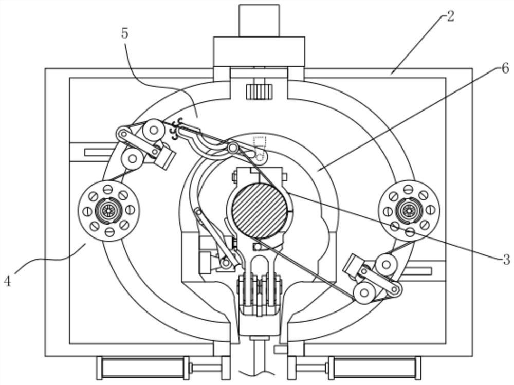
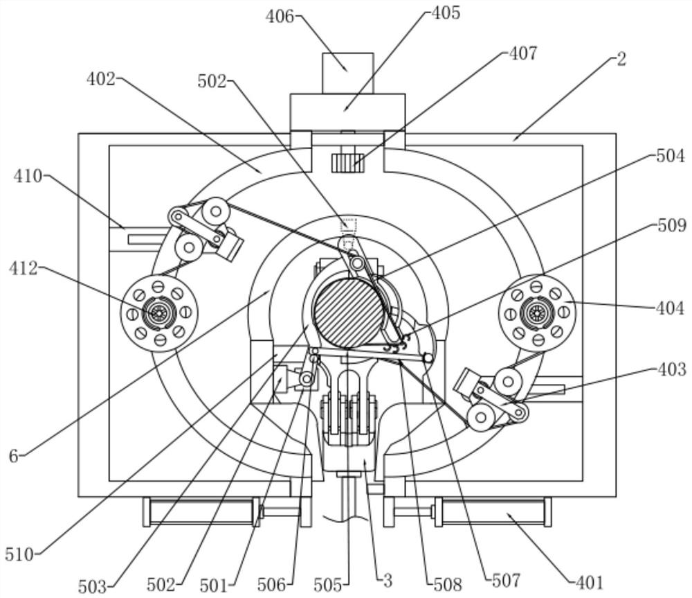
[0024] like Figure 1 to Figure 6 As shown, a steel suspension cable main cable protection device includes a main body 1, a frame 2, a cable clamp 3, a wire winding mechanism 4 and a wire pushing mechanism 5, and the main body 1 is installed on the main suspension cable through a transmission device, The frame 2 is in the shape of a "mouth" and the lower end is open. A mounting seat 6 is installed on the frame 2. The frame 2 is installed on the upper end of the main body 1. There are several cable clips 3 and are evenly distributed on the suspension cables. On the main cable, the wire winding mechanism 4 is installed on the frame 2, and is used to pass the entire wire through the two ends of the cable clamp 3, and the wire pushing me...


PUM


Abstract

The invention discloses a protection device for a main cable of a steel suspension cable, which relates to the technical field of bridge protection equipment and includes a main body, a frame, a cable clamp, a wire winding mechanism and a wire pushing mechanism, and the main body is installed on the main cable of the suspension cable through a transmission device. superior. By setting the wire pushing mechanism and the new type of cable clamp, the present invention eliminates the need for a series of operations such as trimming the end of the wire winding section between the cable clamps, manual winding and welding, etc., thereby improving the degree of automation and the quality of the wire winding. Welding can only be done during the process of replacing the wire storage wheel after the wire wrap is used up, reducing a large number of welded joints and ensuring the long-term effective protection of the main cable by the wire wrap; Finally, in the process of closing the movable part, fill the inside of the storage chamber with coating paint, press the wrapped wire tightly in the wire slot and fill up the inside of the cable clamp, and then completely close the movable part by tightening the wrapped wire at both ends to seal the cable. Openings on both sides of the clip realize further sealing and protection of the inside of the cable clip.

Description

technical field [0001] The invention relates to the technical field of bridge protection equipment, in particular to a steel suspension cable main cable protection equipment. Background technique [0002] A very important part of the main cable protection of the suspension bridge is the main cable winding, which means that the galvanized soft steel wire with a diameter of 3-6mm is densely wound on the surface of the main cable that has been putty layer anti-corrosion treatment. The surface paint forms a permanent protective layer. The existing main cable winding equipment alternately moves on the main cable through the host and the clamping frame. Through the control of the driving equipment and sensors, it can automatically cross the cable clamp and the sling. [0003] However, after using the existing protective equipment for wire wrapping protection, it is found that there are still some drawbacks: 1. When the main machine travels to the front and rear of the cable clip a...

Claims


Application Information

Patent Timeline
Patent Type & Authority Patents(China)
IPC IPC(8): B65H54/22E01D22/00E01D19/16E01D101/30
CPCE01D22/00E01D19/16E01D2101/30
Inventor 郭开振徐安林潘天鸿
Owner 振林建设集团股份有限公司
Why Eureka
Try Eureka