Eureka AIR delivers breakthrough ideas for toughest innovation challenges, trusted by R&D personnel around the world.

Anti-scouring energy dissipation wall of hydraulic engineering overflow dam

A technology for water conservancy projects and overflow dams, which can be used in water conservancy projects, dams, marine engineering and other directions to solve problems such as scouring of buildings.

Active Publication Date: 2021-02-23
安徽坤耀水利建设工程有限公司
View PDF4 Cites 1 Cited by
  • Summary
  • Abstract
  • Description
  • Claims
  • Application Information

AI Technical Summary

Problems solved by technology

[0004] In view of the related technologies mentioned above, the inventor believes that: when the flood is large, the water flow at the bottom still has more kinetic energy after the water flow passes over the energy dissipation wall, which will still cause serious erosion to the building

Method used


Image

  • Anti-scouring energy dissipation wall of hydraulic engineering overflow dam
  • Anti-scouring energy dissipation wall of hydraulic engineering overflow dam

Examples


Embodiment Construction

[0030] The following is attached Figure 1-2 The application is described in further detail.

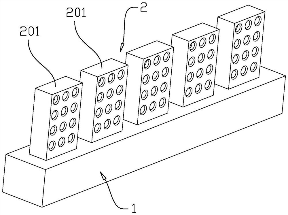
[0031] The embodiment of the application discloses an anti-scouring energy-dissipating wall of an overflow dam of a water conservancy project. refer to figure 1 , the energy dissipation wall includes the foundation 1 poured in concrete in the river bed and the retaining wall 2 fixed on the foundation 1, the foundation 1 is in the shape of a cuboid, the length direction of the foundation 1 is perpendicular to the impact direction of the water flow, and the retaining wall 2 consists of It is composed of several unit walls 201, and the several unit walls 201 are uniformly distributed along the length direction of the foundation 1, and gaps are left between two adjacent unit walls 201. A plurality of unit walls 201 are used to form the retaining wall 2, and when the water flow passes through the retaining wall 2, part of the water flow will pass through the gap between two adjacent uni...


PUM


Abstract

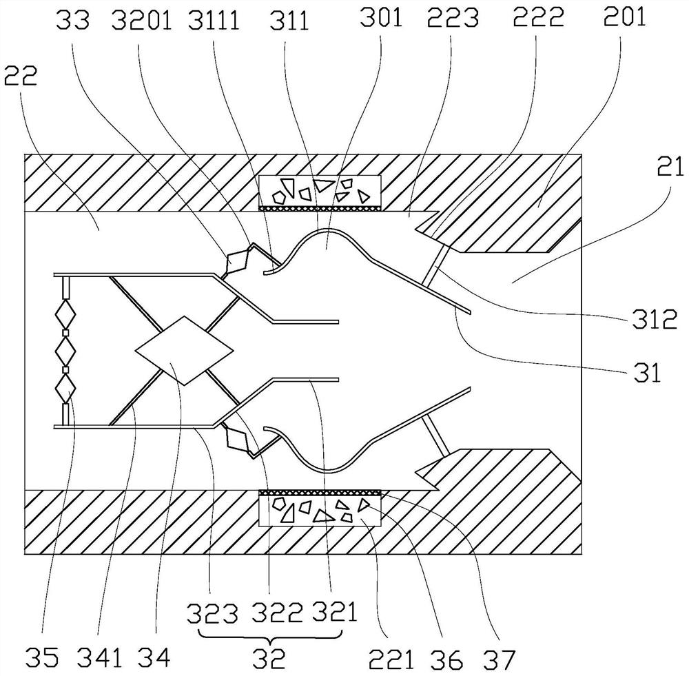
The invention relates to an anti-scouring energy dissipation wall. The anti-scouring energy dissipation wall comprises a flow blocking wall arranged in a foundation, a plurality of energy dissipationholes are formed in the flow blocking wall, energy dissipation grooves are formed in the ends, close to water outlets, of the energy dissipation holes along the circumferences of the inner walls of the energy dissipation holes, energy dissipation assemblies are arranged in the energy dissipation holes and the energy dissipation grooves and comprise flow dividing pipes and energy dissipation pipes,one ends of the flow dividing pipes are located in the energy dissipation holes, the other ends of the flow dividing pipes are located in the energy dissipation grooves, the ends, close to the energydissipation grooves, of the flow dividing pipes protrude to form energy dissipation shoulders, rotary rolling areas are formed on the sides, away from the energy dissipation grooves, of the energy dissipation shoulders, first supporting rods are fixedly connected between the flow dividing pipes and the energy dissipation holes, the energy dissipation pipes comprise inner straight pipes, flow dividing pipes and outer straight pipes which are connected end to end in sequence, the inner straight pipes are located below the rotary rolling areas, the drainage pipes are located below the tail of the energy dissipation shoulders, the diameter of the ends, close to the inner straight pipes, of the drainage pipes is larger than that of the other ends, and second supporting rods are fixedly connected between the flow dividing pipes and the energy dissipation pipes. According to the anti-scouring energy dissipation wall of the hydraulic engineering overflow dam, water flow kinetic energy can beeliminated quickly, and scouring to a building is reduced.

Description

technical field [0001] The application relates to the field of water conservancy engineering, in particular to an anti-scouring energy dissipation wall of an overflow dam of a water conservancy project. Background technique [0002] Water conservancy engineering is a general term for various engineering constructions built to control, utilize and protect surface and underground water resources and the environment. In the construction of water conservancy projects, the energy dissipation wall can eliminate the excess kinetic energy of the rapid discharge of the discharge structure or the drop structure, and prevent or reduce the erosion and damage of the water flow to the hydraulic structure and its downstream canals. The principle of energy dissipation is to set up a stilling pool, a stilling sill, and an energy-dissipating wall at the downstream of the water-retaining building, so as to promote the water flow to generate a hydraulic jump within a limited range, and consume ...

Claims


Application Information

Patent Timeline
IPC IPC(8): E02B3/10E02B8/06
CPCE02B3/10E02B8/06Y02A10/11
Inventor 陈曦张玮苏成启陈家满陈家文
Owner 安徽坤耀水利建设工程有限公司
Why Eureka
Eureka Blog
Learn More