
Intelligent heat preservation formwork cast-in-place concrete cavity-free composite wall heat preservation system

A technology of thermal insulation formwork and composite wall, applied in thermal insulation, wall, visible signal device and other directions, can solve the problems of inability to adjust the spacing of wall panels, inability to intelligently warn at night, poor thermal insulation and noise reduction effect, etc., to ensure convenient disassembly and installation The effect of ensuring the stability of fixation and easy disassembly

Active Publication Date: 2021-02-23
菏泽市定陶区祥明节能保温材料有限公司
View PDF8 Cites 1 Cited by
  • Summary
  • Abstract
  • Description
  • Claims
  • Application Information

AI Technical Summary

Problems solved by technology

[0006] In order to solve the above-mentioned technical problems, the present invention provides an intelligent thermal insulation formwork cast-in-place concrete cavity-free composite wall thermal insulation system to solve the problem that the existing thermal insulation wall cannot adjust the distance between the wall panels, cannot intelligently warn at night, and the thermal insulation drops. Poor noise effect and inconvenient installation and fixation

Method used


Image

  • Intelligent heat preservation formwork cast-in-place concrete cavity-free composite wall heat preservation system
  • Intelligent heat preservation formwork cast-in-place concrete cavity-free composite wall heat preservation system
  • Intelligent heat preservation formwork cast-in-place concrete cavity-free composite wall heat preservation system

Examples


Embodiment Construction

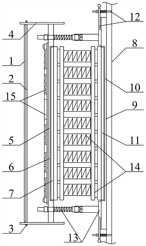
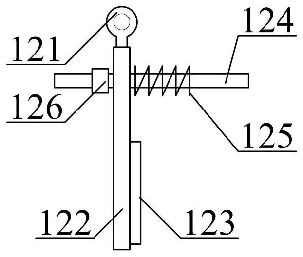
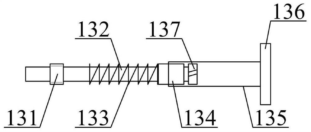
[0034] The present invention is described in detail below in conjunction with accompanying drawing, as appended figure 1 And attached figure 2As shown, the intelligent thermal insulation formwork cast-in-place concrete cavity-free composite wall insulation system includes a transparent plate 1, a light-transmitting plate 2, a fixing bolt 3, an installation guard plate 4, a primary thermal insulation formwork 5, and a primary card slot 6. First-level block 7, building wall 8, second-level insulation formwork 9, second-level card slot 10, second-level block 11, rotary quick-installation clamp structure 12, adjustable spacing support rod structure 13, buffer noise reduction The sound insulation board structure 14 and the intelligent detection auxiliary warning cover structure 15 at night, the transparent board 1 is longitudinally screwed on the left surface of the light-transmitting board 2; The inner left part between them; the horizontal right end bolts of the installation gu...


PUM


Abstract

The invention provides an intelligent heat preservation formwork cast-in-place concrete cavity-free composite wall heat preservation system. The intelligent heat preservation formwork cast-in-place concrete cavity-free composite wall heat preservation system comprises a transparent plate, a light-transmitting plate, fixing bolts, installation protection plates, a first-stage heat preservation formwork, a first-stage clamping groove, a first-stage clamping block, a building wall and a second-stage heat preservation formwork, wherein the transparent plate is longitudinally connected to the leftsurface of the light-transmitting plate through screws; and the light-transmitting plate is longitudinally installed on the left part of the inner side between the installation protection plates through the fixing bolts. By arranging a rotary wristband, a rotary clamping plate, an anti-skid pad, an expansion screw, a pressure spring and a quick-release nut, the rotary clamping plate can be rotatedto act on the outer wall of the expansion screw by loosening the quick-release nut, then the second-stage heat preservation formwork is placed on the outer wall of the building wall, at the moment, the rotary clamping plate is rotated back and makes contact with the second-stage heat preservation formwork through the anti-skid pad, the quick-release nut is screwed down, so that the pressure spring is subjected to energy release buffering and fixing, the fixing stability is guaranteed, and the expansion screw is embedded into the building wall in advance, so that the disassembly and assembly convenience is guaranteed.

Description

technical field [0001] The invention belongs to the technical field of buildings, and in particular relates to an intelligent insulation formwork cast-in-place concrete cavity-free composite wall insulation system. Background technique [0002] Most of the insulation walls need to be built on-site with insulation materials. [0003] At present, a small number of insulation walls are built with prefabricated insulation wall panels. [0004] However, the existing thermal insulation walls still have the problems of being unable to adjust the distance between the wall panels, unable to provide intelligent warning at night, poor thermal insulation and noise reduction effects, and inconvenient to install and fix. [0005] Therefore, it is very necessary to invent an intelligent insulation formwork cast-in-place concrete cavity-free composite wall insulation system. Contents of the invention [0006] In order to solve the above-mentioned technical problems, the present inventio...

Claims


Application Information

Patent Timeline
Patent Type & Authority Applications(China)
IPC IPC(8): E04B2/84E04B2/86E04B1/76E04B1/88G08B5/36
CPCE04B1/76E04B1/7629E04B1/88E04B2/84E04B2/86G08B5/36
Inventor 葛威
Owner 菏泽市定陶区祥明节能保温材料有限公司
Learn More