
Energy-saving electric control valve and electric control fuel system

A fuel system and electronically controlled valve technology, which is applied in the layout, lift valve, valve details, etc. combined with the fuel supply of the internal combustion engine, can solve the problems of difficult control of different components, low integration, and low steam management accuracy, and achieve rapid response. , to avoid the effect of overloading and reducing environmental pollution

Pending Publication Date: 2021-02-23
YAPP AUTOMOTIVE PARTS
View PDF2 Cites 5 Cited by
  • Summary
  • Abstract
  • Description
  • Claims
  • Application Information

AI Technical Summary

Problems solved by technology

[0005] The purpose of the present invention is to provide an energy-saving electronically controlled valve and electronically controlled fuel system to solve the problems of low steam management accuracy, low integration and difficult regulation of different components in the existing fuel system, and to improve the control accuracy of the fuel system. Detect potential leaks in the fuel system and reduce environmental pollution

Method used


Image

  • Energy-saving electric control valve and electric control fuel system
  • Energy-saving electric control valve and electric control fuel system
  • Energy-saving electric control valve and electric control fuel system

Examples


Embodiment Construction

[0034] The technical solution of the present application is described in detail through the following examples. The following examples are only exemplary, and can only be used to explain and illustrate the technical solution of the present invention, and cannot be interpreted as limitations to the technical solution of the present invention.

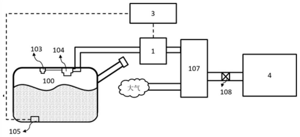
[0035] Such as figure 1 It is a schematic diagram of the prior art. There is a fuel tank isolation valve 1 between the fuel tank and the carbon tank, and a carbon tank isolation valve 2 between the carbon tank and the atmosphere. The two valves are independent components. The fuel tank isolation valve has the purpose of isolating the fuel tank and also has the function of opening and closing, which is suitable for different working conditions. The canister isolation valve is used to open and close the passage of atmosphere to the canister. The fuel tank isolation valve and the carbon canister isolation valve are controlled separately by...


PUM


Abstract

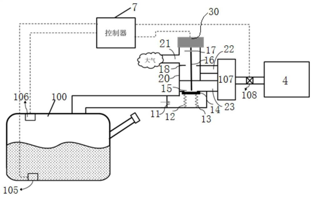
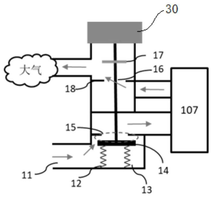
The invention relates to an energy-saving electric control valve and an electric control fuel system. The energy-saving electric control valve comprises a shell, a driving source, a guide rod, a firstvalve element, a second valve element and a compressible component. The electric control fuel system comprises a fuel tank, a liquid level sensor, a pressure sensor, a carbon tank and a controller. The liquid level sensor, the pressure sensor and the energy-saving electric control valve are all in electric signal connection with the controller. A first connecting port in the energy-saving electric control valve is connected with an exhaust port in the fuel tank, a second connecting port is connected with an air inlet in the carbon tank, a third connecting port is connected with an atmosphericpipeline, and a fourth connecting port is connected with an exhaust port in the carbon tank. According to the energy-saving electric control valve and the electric control fuel system, with the energy-saving electric control valve, communication between the fuel tank and the carbon tank is cut off, it is avoided that oil vapor enters the carbon tank and causes overlarge load of the carbon tank, and less environmental pollution is caused; and the opening degree of a channel can be controlled by controlling the moving distance of a driving source, and the volume is accurately controlled in theprocess of filling and supplementing fuel oil.

Description

technical field [0001] The invention relates to the technical field of fuel tanks, in particular to an energy-saving electric control valve and an electric control fuel system. The electric control fuel system takes the electric control valve as the core, and the electric control fuel system is adapted to different vehicles by adjusting the electric control valve. It realizes functions such as controllable fuel filling, vapor emission management, and on-board diagnostic system (OBD) detection. Background technique [0002] In order to meet the increasingly stringent laws and regulations, under certain conditions, it is necessary to seal the fuel gas in the fuel system and use the fuel tank isolation valve to control. The interactive change of the ambient temperature will cause the pressure inside the fuel tank to also change interactively. If the pressure exceeds a certain range, it will cause The deformation of the fuel tank is too large, so the fuel tank isolation valve ha...

Claims


Application Information

Patent Timeline
Patent Type & Authority Applications(China)
IPC IPC(8): F16K11/22F16K1/36F16K27/02F16K37/00B60K15/035
CPCF16K11/22F16K1/36F16K27/0263F16K37/0091B60K15/035B60K2015/03576B60K2015/03566
Inventor 周传军姜林高德俊吕昊张艳波严济彦刘亚洲李建东
Owner YAPP AUTOMOTIVE PARTS
Learn More