Waterproof convenient-to-install automatic instrument
A waterproof, instrument technology, applied to the locking device, instrument, measuring device and other directions when the movable parts of the measuring device are not in use, can solve problems such as inconvenient operation, achieve variable viewing angles, improve work efficiency, and facilitate operation. Effect
- Summary
- Abstract
- Description
- Claims
- Application Information
AI Technical Summary
Problems solved by technology
Method used
Image
Examples
Embodiment 1
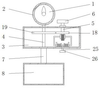
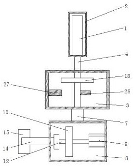
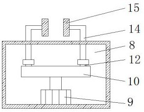
[0030] Example 1 as figure 1 , 2 , 3, 4, 5, 7, and 8, according to an embodiment of the present invention, a waterproof and easy-to-install automatic instrument includes an instrument body 1, and a waterproof casing 2 is provided outside the instrument body 1, and the waterproof casing One side of 2 is provided with a rear cover 16, and the rear cover 16 is provided with several bolts 17, and the bottom of the waterproof casing 2 is provided with a rotary box 3, and the waterproof casing 2 and the rotary box 3 are connected by a rotating rod 4 are movably connected, the top of the rotating box 3 is movably connected with a rotating shaft 5 through a bearing, the top of the rotating shaft 5 is fixedly connected with a rotating handle 6, and the rotating rod 4 and the rotating shaft 5 are provided with Transmission mechanism, the bottom end of the rotating shaft 5 is provided with a clamping mechanism, the bottom end of the rotating box 3 is fixedly connected with a clamping bo...
Embodiment 2
[0032] Embodiment 2 is on the basis of embodiment 1 such as figure 1 As shown, for the transmission mechanism, the transmission mechanism includes gear one 18 and gear two 19, the surface of the rotating shaft 5 is fixedly connected with gear one 18, and the gear one 18 meshes with gear two 19, and the gear two The shaft center of 19 is fixedly connected with described rotating rod one 4.
[0033] Through the above-mentioned scheme of the present invention, the meshing of the first gear 18 and the second gear 19 can drive the instrument to rotate by turning the handle one 6 .
Embodiment 3
[0034] Embodiment 3 is such as on the basis of embodiment 1 Figure 4-5 As shown, for the clamping mechanism, the clamping mechanism includes a fixed block 13, a slider 20, a spring 21, a U-shaped bar 22 and a splint 23, and two fixed blocks are symmetrically arranged at the inner bottom of the rotating box 3 13. A U-shaped bar 22 is slidably connected inside the fixed block 13, a slider 20 is fixedly connected to one end of the U-shaped bar 22 close to the fixed block 13, and a splint is fixedly connected to the other end of the U-shaped bar 22 23. A groove is provided on the surface of the splint 23, a spring 21 is connected between the slider 20 and the U-shaped bar 22, the spring 21 is wound on the surface of the U-shaped bar 22, and the slider 20 There is a rotating mechanism between them.
[0035] Through the above solution of the present invention, the splint 23 clamps the rotating shaft 5, so that the instrument can be stable when it does not need to rotate.
PUM
 Abstract
Description
Claims
Application Information
 - R&D
- Intellectual Property
- Life Sciences
- Materials
- Tech Scout
- Unparalleled Data Quality
- Higher Quality Content
- 60% Fewer Hallucinations
Browse by: Latest US Patents, China's latest patents, Technical Efficacy Thesaurus, Application Domain, Technology Topic, Popular Technical Reports.
© 2025 PatSnap. All rights reserved.Legal|Privacy policy|Modern Slavery Act Transparency Statement|Sitemap|About US| Contact US: help@patsnap.com


