Cross-flow fan blade drop test tool

A cross-flow fan blade and testing tooling technology, which is applied in the direction of measuring devices, impact tests, machine/structural component testing, etc., can solve the problem that testers cannot directly observe the height of the steel shaft and the ground, and it is difficult to control the verticality of the wind blade and the ground , It is difficult to solve the problems such as the height of the steel shaft of the fan blade, so as to reduce the waste of human resources, improve the convenience of operation, and improve the efficiency and accuracy.

Pending Publication Date: 2021-02-23
GREE ELECTRIC APPLIANCES WUHAN +1
View PDF0 Cites 1 Cited by
  • Summary
  • Abstract
  • Description
  • Claims
  • Application Information

AI Technical Summary

Problems solved by technology

Because the height required for the test is low, and the wind blades are generally long, the tester cannot directly observe the height between the steel shaft and the ground during the single-person test, making it difficult to accurately control the height of the steel shaft of the wind blade from the ground. It has a great impact on the accuracy of the test. Generally, two people are required to assist in completing the test, which is inconvenient.
In addition, it is difficult to control the verticality between the blade and the ground by manually holding the blade, which also affects the accuracy of the test.

Method used


Image

  • Cross-flow fan blade drop test tool
  • Cross-flow fan blade drop test tool
  • Cross-flow fan blade drop test tool

Examples


Embodiment Construction

[0037] The present invention will be further described below in conjunction with accompanying drawing.

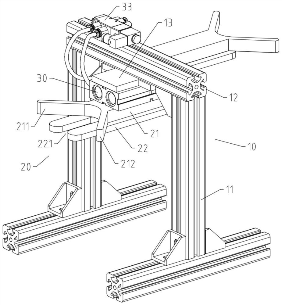
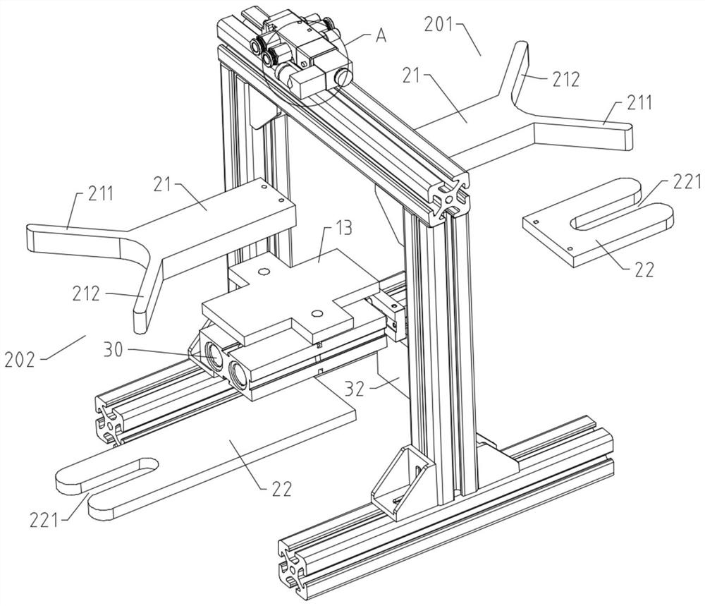
[0038] The present invention provides a cross-flow fan blade drop test tool, including:

[0039] bracket 10;

[0040] The supporting assembly 20, the supporting assembly 20 includes a baffle 21 and a supporting plate 22 overlapped from top to bottom, the baffle 21 is fixedly connected with the bracket 10, and one end of the supporting plate 22 has a strip-shaped gap 221, where the gap 221 is located. The end of supporting plate 22 is U-shaped;

[0041] The power assembly 30, the power assembly 30 is fixed on the bracket 10, the power assembly 30 has a movable part 31, the movable part 31 is connected to the supporting plate 22 and can drive the supporting plate 22 to translate along the length direction of the notch 221;

[0042] Wherein, when the cross-flow fan blade is placed on the support plate 22, the steel shaft of the cross-flow fan blade is located in the gap 221,...


PUM


Abstract

The invention provides a cross-flow fan blade drop test tool. The cross-flow fan blade drop test tool comprises a support, a bearing assembly and a power assembly; the bearing assembly comprises a baffle and a supporting plate which are arranged in an overlapped mode from top to bottom, the baffle is fixedly connected with the support, and a strip-shaped notch is formed in one end of the supporting plate; the power assembly is fixed to the support, the power assembly is provided with a movable part, and the movable part is connected with the supporting plate and can drive the supporting plateto horizontally move in the length direction of the notch; and when cross-flow fan blades are placed on the supporting plate, the edge of the baffle makes contact with the outer surfaces of the circumferences of the cross-flow fan blades. Based on the technical scheme of the invention, through the cooperation of the bearing assembly and the power assembly, the supporting of the supporting plate and the automatic separation of the tested fan blade are realized, the manual labor is reduced, the verticality of the tested fan blade during falling is ensured, and the test efficiency and accuracy are greatly improved.

Description

technical field [0001] The invention relates to the technical field of air conditioning, in particular to a cross-flow fan blade drop test tool. Background technique [0002] The cross-flow fan blade is an important part of the air conditioner. The firmness of the connection between the steel shaft and the end cover directly determines whether the fan blade can maintain the integrity of the structure during the transportation of the air conditioner and whether it can be used normally during long-term use. In order to test the strength of the joint between the steel shaft and the end cover, a vertical drop test will be carried out during the production process of the cross-flow fan blade. The vertical drop test method of the steel shaft of the cross-flow fan blade is as follows: [0003] First, fix the sleeve end of the cross-flow fan blade so that the axial direction of the fan blade is perpendicular to the ground, and the steel shaft end is downward, and lift the fan blade ...

Claims


Application Information

Patent Timeline
Patent Type & Authority Applications(China)
IPC IPC(8): G01M7/08
CPCG01M7/08
Inventor 吴绮玥翟志强康扬刘爽
Owner GREE ELECTRIC APPLIANCES WUHAN
Why Eureka
Try Eureka