Unlock instant, AI-driven research and patent intelligence for your innovation.
Clamping device for PCB production
What is Al technical title?
Al technical title is built by PatSnap Al team. It summarizes the technical point description of the patent document.
A technology for PCB boards and clamping devices, which is applied in the field of clamping devices for PCB board production, and can solve problems such as inconvenient PCB board handling
Pending Publication Date: 2021-02-23
AOSHIKANG TECH CO LTD
View PDF0 Cites 0 Cited by
Summary
Abstract
Description
Claims
Application Information
AI Technical Summary
This helps you quickly interpret patents by identifying the three key elements:
Problems solved by technology
Method used
Benefits of technology
Problems solved by technology
[0003] At present, during the production and processing of PCB boards, many links need to clamp and fix the PCB boards to prevent the misalignment of the PCB boards during processing and affect the quality of the PCB boards. However, most of the existing clamping devices for PCB board production Clamping on both sides is used, which is inconvenient to handle the two sides of the PCB board clamping
Method used
Image
Click on the blue label to locate the original text in one second.
Reading with bidirectional positioning of images and text.
Examples
no. 1 example
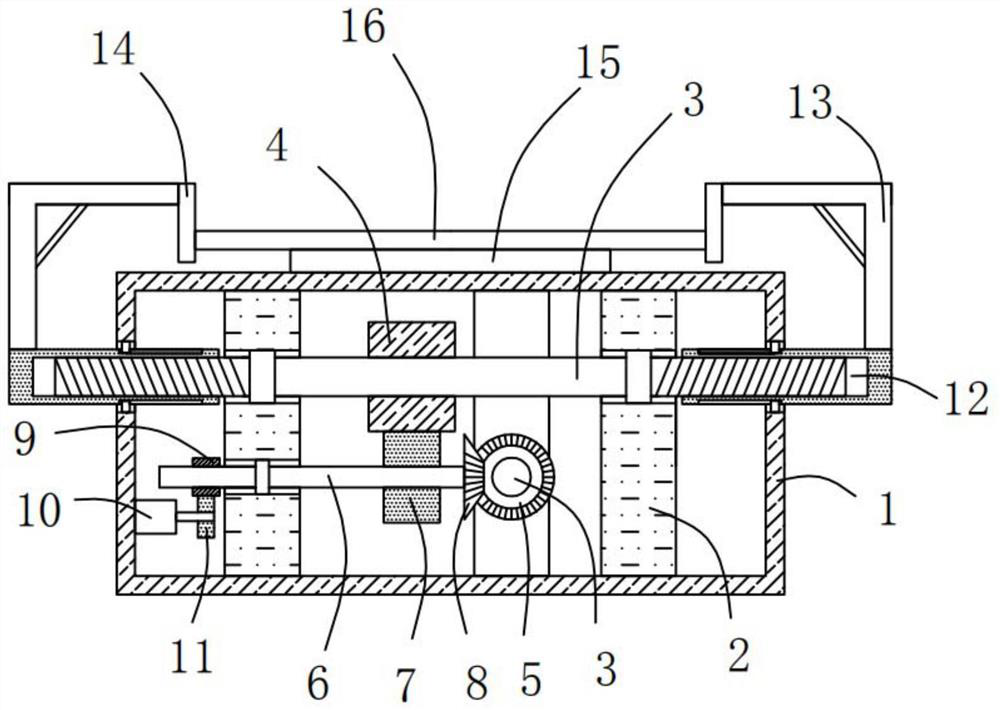
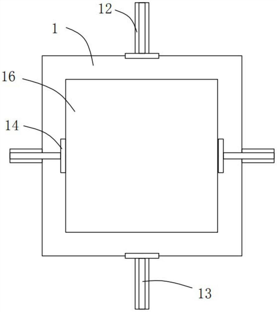
[0040] Please refer to figure 1 and figure 2 , in the first embodiment of the present invention, the clamping device for PCB board production includes: a support box 1;
[0041] Four support blocks 2, the four support blocks 2 are all fixedly installed in the support box 1;
[0042] A rotating rod 3, the two rotating rods 3 are respectively connected to the two corresponding two supporting blocks 2 in rotation;
[0043] The first gear 4, the first gear 4 is fixedly sleeved on the outside of one of the rotating rods 3;
[0044] The first bevel gear 5, the first bevel gear 5 is fixedly sleeved on the outside of the other rotating rod 3;
[0045] Active lever 6, said active lever 6 is rotatably mounted on the corresponding support block 2;
[0046] The second gear 7, the second gear 7 is fixedly sleeved on the outside of the active rod 6, and the second gear 7 is meshed with the first gear 4;
[0047] The second bevel gear 8, the second bevel gear 8 is fixedly sleeved on th...
no. 2 example
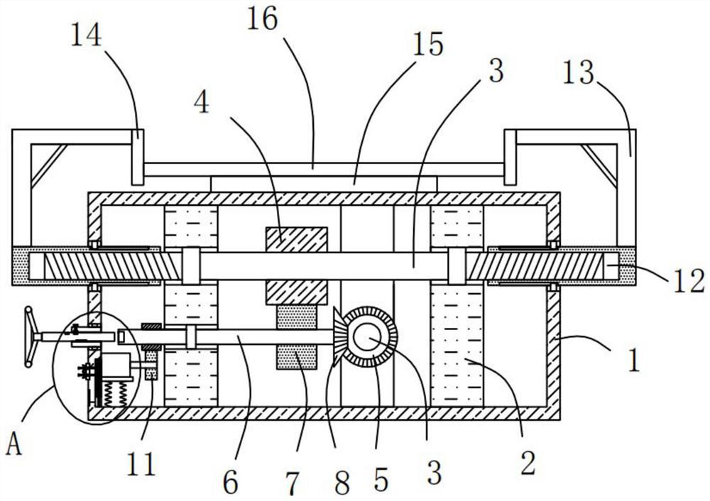
[0063] Based on the clamping device for PCB board production provided in the first embodiment of the present application, the second embodiment of the present application proposes another clamping device for PCB board production. The second embodiment is only a preferred mode of the first embodiment, and the implementation of the second embodiment will not affect the independent implementation of the first embodiment.
[0064] The second embodiment of the present invention will be further described below in conjunction with the drawings and implementation methods.
[0065] Please refer to Figure 3-6 The clamping device for PCB board production also includes a connection groove 17 opened at one end of the active rod 6, the connection groove 17 is a polygonal groove, and a sleeve 18 is installed on one side of the support box 1 for rotation. One end of the sleeve 18 extends into the support box 1, a slide bar 19 is slidably installed in the sleeve 18, the slide bar 19 is adapt...
PUM
Abstract
The invention provides a clamping device for PCB production. The clamping device for PCB production comprises a supporting box; four supporting blocks which are all fixedly mounted in the supporting box; two rotating rods which are rotationally connected with two corresponding supporting blocks respectively; a first gear which is fixedly arranged on the outer side of one of the rotating rods in asleeving mode; a first bevel gear which is fixedly arranged on the outer side of the other rotating rod in a sleeving mode; a driving rod installed on the corresponding supporting block in a rotatingmode; and a second gear which is fixedly arranged on the outer side of the driving rod in a sleeving mode, wherein the second gear is engaged with the first gear. The clamping device for PCB production has the advantages of being convenient to use and capable of conveniently processing the four sides of a PCB.
Description
technical field [0001] The invention relates to the technical field of PCB board processing, in particular to a clamping device for PCB board production. Background technique [0002] PCB board, also known as printed circuit board, is the provider of electrical connection for electronic components. Its development has a history of more than 100 years; its design is mainly layout design; the main advantage of using circuit boards is that it greatly reduces wiring and assembly errors, and improves automation and production labor rates. [0003] At present, during the production and processing of PCB boards, many links need to clamp and fix the PCB boards to prevent the misalignment of the PCB boards during processing and affect the quality of the PCB boards. However, most of the existing clamping devices for PCB board production Clamping on both sides is adopted, which is inconvenient to handle the two sides of the PCB board clamping. [0004] Therefore, it is necessary to p...
Claims
Application Information
Patent Timeline
Application Date:The date an application was filed.
Publication Date:The date a patent or application was officially published.
First Publication Date:The earliest publication date of a patent with the same application number.
Issue Date:Publication date of the patent grant document.
PCT Entry Date:The Entry date of PCT National Phase.
Estimated Expiry Date:The statutory expiry date of a patent right according to the Patent Law, and it is the longest term of protection that the patent right can achieve without the termination of the patent right due to other reasons(Term extension factor has been taken into account ).
Invalid Date:Actual expiry date is based on effective date or publication date of legal transaction data of invalid patent.

