Uniform and quantitative fertilizing device for agricultural planting
A quantitative and uniform fertilization technology, applied in fertilization devices, agriculture, agricultural machinery and tools, etc., can solve the problems of loss of beneficial elements of organic fertilizers, unfavorable plant nutrient absorption, and blockage of feeding ports, so as to achieve uniform nutrient distribution and quantitative The effect of feeding and preventing clogging
- Summary
- Abstract
- Description
- Claims
- Application Information
AI Technical Summary
Problems solved by technology
Method used
Image
Examples
Embodiment 1
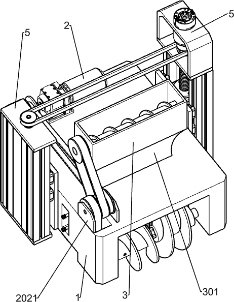
[0030] A uniform and quantitative fertilization device for agricultural planting, such as Figure 1-5 and Figure 7-8 As shown, it includes a vehicle frame 1, a power mechanism, a feeding mechanism and a soil-turning mechanism. Connected with the power mechanism, the soil-turning mechanism is installed on the lower front side of the vehicle frame 1, the soil-turning mechanism is slidingly connected with the blanking mechanism, and the soil-turning mechanism is connected with the power mechanism.
[0031] When using the device for fertilization, manually put the fertilizer into the feeding mechanism, start the power mechanism, the power mechanism takes the soil turning mechanism to carry out the process of loosening the soil, the power mechanism takes the feeding mechanism to carry out the fertilization process, and then the follow-up of the feeding mechanism Partially shake the soil, cover the fertilizer, and complete the entire fertilization process.
Embodiment 2
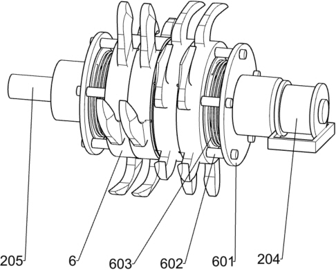
[0033] On the basis of Example 1, such as image 3 As shown, the power mechanism includes a first motor 2, a first pulley 201, a second pulley 202, a fixed plate 2021, a first belt 203, a third pulley 204, a shaft 205, a second belt 206, a spline Shaft 207, the fourth pulley 208, the third belt 209, the first screw rod 210, the fifth pulley 211 and the fourth belt 212, the first motor 2 is fixedly installed on the upper rear side of the vehicle frame 1, the first pulley 201 Fixedly installed on the output shaft of the first motor 2, two fixed plates 2021 are fixedly installed on the upper front side of the vehicle frame 1, the second pulley 202 is rotatably installed between the two fixed plates 2021, and the first belt 203 is wound around On the first pulley 201 and the second pulley 202, the third pulley 204 on the upper side is fixedly installed on the left side of the output shaft of the first motor 2, and the shaft rod 205 is rotatably installed on the lower rear side of ...
Embodiment 3
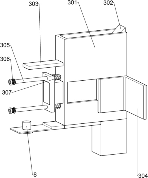
[0036] On the basis of Example 2, such as Figure 4-6 As shown, the blanking mechanism includes a material frame 3, a fixed frame 301, an inclined block 302, a guide plate 303, a slide plate 304, a first sliding column 305, a first spring 306, a second spring 307 and a second screw rod 4, and the fixed frame 301 Fixedly installed on the upper part of the vehicle frame 1 close to the middle position, the material frame 3 is fixedly installed on the upper side of the fixed frame 301, the first screw rod 210 is rotatably installed on the left and right sides inside the material frame 3, and the oblique block 302 is fixedly installed on the upper part of the vehicle frame 1 On the front side, the oblique block 302 is fixedly installed inside the fixed frame 301, two slide plates 304 are slidably installed inside the fixed frame 301, and two pairs of first sliding columns 305 are fixedly installed on the left and right sides of the fixed frame 301 respectively, and the first slide ...
PUM
 Abstract
Description
Claims
Application Information
 - R&D
- Intellectual Property
- Life Sciences
- Materials
- Tech Scout
- Unparalleled Data Quality
- Higher Quality Content
- 60% Fewer Hallucinations
Browse by: Latest US Patents, China's latest patents, Technical Efficacy Thesaurus, Application Domain, Technology Topic, Popular Technical Reports.
© 2025 PatSnap. All rights reserved.Legal|Privacy policy|Modern Slavery Act Transparency Statement|Sitemap|About US| Contact US: help@patsnap.com


