Purification system and purification method for volatile pollutants

A volatile pollutant and purification system technology, applied in the field of purification, can solve the problems of high economic cost, complex process, low efficiency, etc., and achieve the effect of saving electric energy, simple structure and convenient installation

Inactive Publication Date: 2021-02-26
SHANGHAI PUDONG ROAD & BRIDGE GRP CO LTD
View PDF10 Cites 1 Cited by
  • Summary
  • Abstract
  • Description
  • Claims
  • Application Information

AI Technical Summary

Problems solved by technology

[0003] At present, adsorption, thermal desorption and other technical processes are mainly used to separate the residual state or free state pollutants from the soil in the form of volatiles. The process is complex and inefficient, and requires a large amount of adsorption materials and energy, such as activated carbon, Resources such as electric energy have high economic costs, which is not conducive to the development of the soil remediation industry

Method used


Image

  • Purification system and purification method for volatile pollutants
  • Purification system and purification method for volatile pollutants
  • Purification system and purification method for volatile pollutants

Examples


Embodiment 1

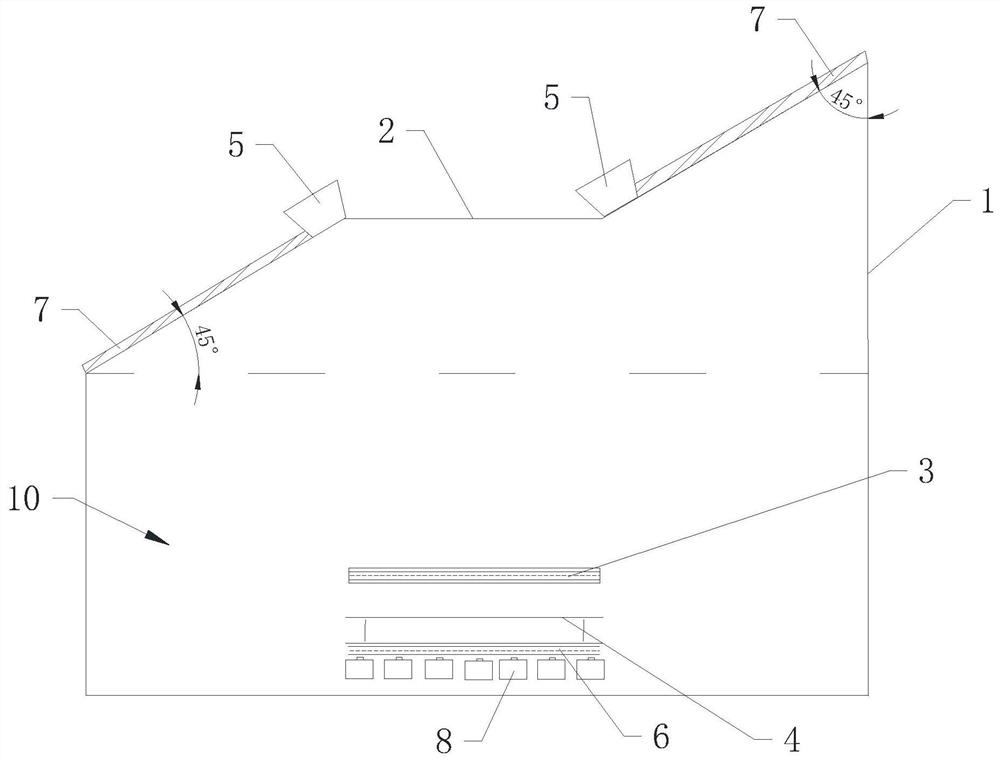
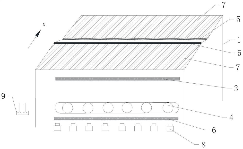
[0044] Reference manual attached Figure 1 to Figure 4 , the present invention provides a purification system of volatile pollutants, the purification system of said volatile pollutants can directly convert light radiation into heat energy or convert light radiation into electric energy first and then into heat energy, so as to remove volatile pollution in soil The process is simple and efficient. Preferably, the pollutant is polluted soil. It can be understood that the pollutant can also be other solid or liquid pollutants, and the specific type of the pollutant should not limit the present invention.

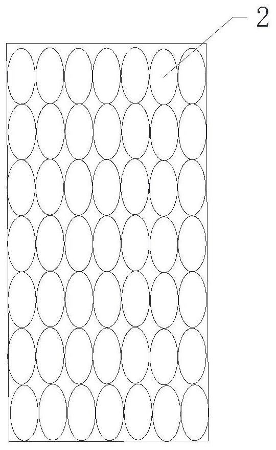
[0045] Reference manual attached figure 1 with figure 2 , specifically, the purification system for volatile pollutants includes a skeleton 1 , a convex lens group 2 , a heat distribution plate 3 , a conveying device 4 and a negative pressure purification device 5 . The frame 1 surrounds and forms a clean space 10; the convex lens group 2 is installed on the frame 1; the h...

Embodiment 2

[0067] According to another aspect of the present invention, the present invention further provides a purification method for volatile pollutants, comprising:

[0068] 101: Transport the pollutants to a preset position through the conveying device 4;

[0069] 102: Heat the pollutants delivered to a preset location, so that volatile pollutants in the pollutants are heated and left;

[0070] 103: extract the volatile pollutants volatilized by the pollutants by heating through the negative pressure purification device 5, and introduce the outside air;

[0071] Wherein, heating the pollutants delivered to the preset position includes:

[0072] Through the convex lens group 2 arranged in the middle position of the top of the frame 1, the light is converged to the heat distribution plate 3 arranged at the focal point of the convex lens group 2, and the heat distribution plate 3 can heat the transmission device 4 in the form of thermal radiation. pollutants; and / or, the pollutants ...


PUM


Abstract

The present invention discloses a purification system and purification method for volatile pollutants. The purification system for the volatile pollutants comprises a skeleton surrounding to form a purification space, a convex lens group arranged on the framework, a heat distribution plate which is located in the purification space and located at the focal point of the convex lens group, a conveying device located below the heat distribution plate and is opposite to the heat distribution plate, and a negative pressure purification device used for extracting volatile pollutants volatilized by heated pollutants and introducing external air into the purification space; light penetrating through the convex lens group irradiates the heat distribution plate, wherein the heat distribution plate is used for heating pollutants on the conveying device in a heat radiation mode, so that volatile pollutants in the pollutants are heated to leave. Light radiation can be directly converted into heat energy or light radiation is firstly converted into electric energy and then converted into heat energy, so that volatile pollutants in soil are removed, and the process is simple and efficient.

Description

technical field [0001] The invention relates to the field of purification, and further relates to a purification system and a purification method for volatile pollutants, in particular to a system and a purification method for purifying volatile pollutants in soil by using light radiation. Background technique [0002] Usually, the types, states and contents of soil pollutants are diverse, complex and uncertain, which brings great difficulties to the remediation work. Among the various states of soil pollutants, the residue state or free state is one of the main states of pollutants, which is also the easiest to remove. [0003] At present, adsorption, thermal desorption and other technical processes are mainly used to separate the residual state or free state pollutants from the soil in the form of volatiles. The process is complex and inefficient, and requires a large amount of adsorption materials and energy, such as activated carbon, Resources such as electric energy ha...

Claims


Application Information

Patent Timeline
Patent Type & Authority Applications(China)
IPC IPC(8): B09C1/06
CPCB09C1/06
Inventor 邓国民施曙东李军代邱轶
Owner SHANGHAI PUDONG ROAD & BRIDGE GRP CO LTD
Why Eureka
Try Eureka