Automatic batch stamping equipment for office documents

A batch and document technology, applied in printing, stamping, etc., can solve problems such as fast working frequency and easy to dirty documents

Pending Publication Date: 2021-02-26
卢普英
View PDF11 Cites 4 Cited by
  • Summary
  • Abstract
  • Description
  • Claims
  • Application Information

AI Technical Summary

Problems solved by technology

[0004] In order to overcome the shortcomings of traditional stamping equipment that work too fast and easily stain documents, the technical problem to be solved is to provide a machine that drives the stamp while filling the ink while stamping, provides a moderate working frequency, and ensures the mass production of the stamp effect. Automatic stamping equipment for office documents

Method used


Image

  • Automatic batch stamping equipment for office documents
  • Automatic batch stamping equipment for office documents
  • Automatic batch stamping equipment for office documents

Examples


Embodiment 1

[0057] A batch of automatic stamping equipment for office documents, such as Figure 1 to Figure 3 As shown, it includes a first support frame 1 , a transmission mechanism 2 and a seal mechanism 3 , the top of the first support frame 1 is provided with a transmission mechanism 2 , and the top of the first support frame 1 is provided with a seal mechanism 3 .

[0058] The transmission mechanism 2 includes a motor 21, a pulley assembly 22, a fixed block 23, a rotating shaft 24, a first missing gear 25, a bevel gear 26, a first transmission assembly 27, a fixed shaft 28 and a projection 29, and the first supporting frame 1 top front A motor 21 is arranged on the side, and the output shaft of the motor 21 is connected with a first missing gear 25, and the left and right sides of the top of the first support frame 1 are connected with fixed blocks 23, and the belt pulley assembly 22 is connected in rotation between the fixed blocks 23, The front side of the drive shaft on the right...

Embodiment 2

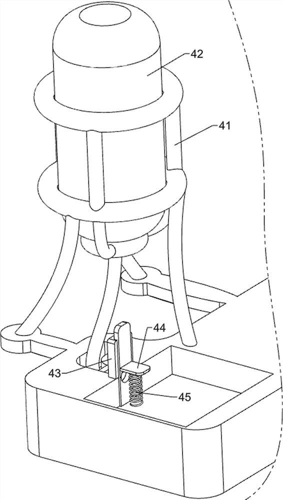
[0062] On the basis of Example 1, such as Figure 4 with Figure 5 As shown, the initial state also includes an ink filling mechanism 4, and the ink adding mechanism 4 includes a second support frame 41, an ink barrel 42, a chute block 43, a stopper 44 and a second spring 45, and the top of the first support frame 1 The left rear side is connected with a second support frame 41, the second support frame 41 is provided with an ink barrel 42, the bottom of the ink barrel 42 is connected with an ink outlet pipe, the top of the first support frame 1 is provided with a chute block 43, and the chute block 43 A block 44 is slidably connected to the top, and the block 44 cooperates with the ink outlet pipe. A second spring 45 is connected between the bottom of the block 44 and the top of the first supporting frame 1 .

[0063] The ink in the ink barrel 42 flows into the top of the first support frame 1 through the ink outlet pipe. When the stamp 37 moved backwards and contacted the s...

Embodiment 3

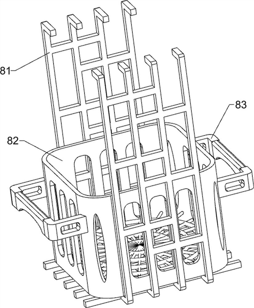
[0067] On the basis of Example 2, such as Figure 6 to Figure 8 As shown, a blanking mechanism 6 is also included, and the blanking mechanism 6 includes a gear set 61, a third support block 62, a first fixed rod 63, a third transmission assembly 64, a second missing gear 65, and a second fixed rod 66 , rack bar 67 and the 4th spring 68, the 3rd support block 62 is provided with the front side of the first support frame 1 top, the 3rd support block 62 left side is connected with the first fixed rod 63, the first fixed rod 63 tops and A gear set 61 is connected between the transmission shafts of the second transmission assembly 33, a third transmission assembly 64 is connected between the gear set 61 and the top of the third support block 62, and a second transmission assembly 64 is connected to the right side of the transmission shaft of the third transmission assembly 64. Missing gear 65, the rear side of the first support frame 1 is connected with a second fixed rod 66, and t...


PUM


Abstract

The invention relates to stamping equipment, in particular to automatic batch stamping equipment for office documents. According to the automatic batch stamping equipment for the office documents, a machine is used for driving a stamp to conduct stamping while inking, the moderate working frequency is provided, and the stamping effect is guaranteed. The automatic batch stamping equipment for the office documents comprises a first supporting frame and a stamping mechanism; a conveying mechanism is arranged at the top of the first supporting frame; and the stamping mechanism is arranged at the top of the first supporting frame. A push plate is arranged to push files, then a rack pressing rod is driven to move downwards to extrude the files, the files are directly fixed to a clamping mechanism, and the situation that the files fall off in the moving process, and the stamping effect is affected is prevented; and the conveying mechanism is arranged for conveying the files and matched with the stamp.

Description

technical field [0001] The invention relates to a stamping device, in particular to an automatic stamping device for batch office documents. Background technique [0002] Seals, also known as stamps, are used as stationery printed on documents to indicate identification or signature. Generally, stamps are first stained with paint and then printed. Those without paint and printed on a flat surface will appear concave and convex. They are called steel seals. Some are printed on Wax seals on wax or wax seals, on envelopes, are made of metal, wood, stone, jade, etc. Modern seals are more stained with paint, that is, stamped. [0003] The traditional stamping equipment consists of an ink pushing mechanism, a stamping mechanism and a placing table. The user needs to place the material on the placing table first, hold one end of the material at the same time, and start the ink pushing mechanism and the stamping mechanism at the same time. The ink pushing mechanism continuously push...

Claims


Application Information

Patent Timeline
Patent Type & Authority Applications(China)
IPC IPC(8): B41K3/04B41K3/46B41K3/48B41K3/54B41K3/62
CPCB41K3/04B41K3/46B41K3/48B41K3/54B41K3/62
Inventor 卢普英
Owner 卢普英
Why Eureka
Try Eureka