Material conveying device

A technology for conveying devices and materials, applied in the direction of conveyors, conveyor objects, mechanical conveyors, etc., can solve the problems of low dissolution efficiency, unqualified products, incomplete dissolution of raw materials, etc., achieve good dissolution effect and prevent clogging Effect

Active Publication Date: 2021-02-26
常州德匠数控科技有限公司 +1
View PDF6 Cites 2 Cited by
  • Summary
  • Abstract
  • Description
  • Claims
  • Application Information

AI Technical Summary

Problems solved by technology

[0003] Among them, the above-mentioned material conveying device cannot increase the dissolution efficiency of raw materials during use, and often in the actual use process, raw material dissolution is incom

Method used


Image

  • Material conveying device
  • Material conveying device
  • Material conveying device

Examples


Embodiment Construction

[0034] The present invention is described in further detail now in conjunction with accompanying drawing. These drawings are all simplified schematic diagrams, which only illustrate the basic structure of the present invention in a schematic manner, so they only show the configurations related to the present invention.

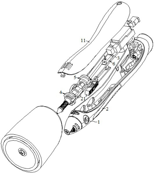
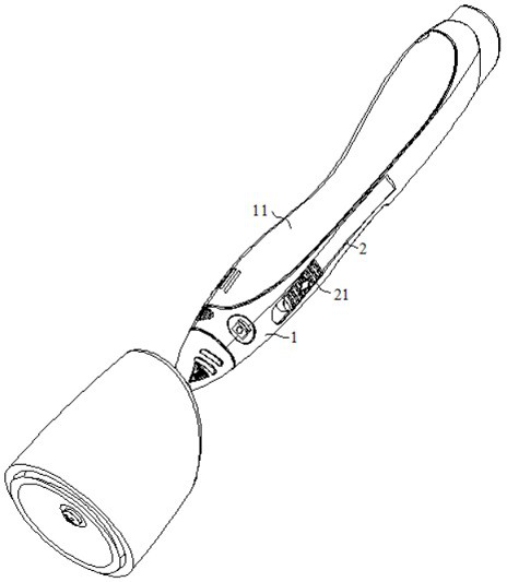
[0035] Such as Figure 1-12 As shown, it is an integral material conveying device. The material conveying device has a material outlet and a material inlet respectively. The middle part of the device is melted;

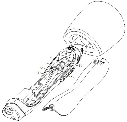
[0036] However, often in the process of actual use, since the raw material needs to be heated after it penetrates into the support plate 3 inside the conveying base 1, during the heating process, the phenomenon of low heating efficiency or incomplete heating may occur. , and after the end of use, there is a problem that the raw material inside the conveying base 1 cannot be cut off quickly to prevent the conveying base 1 from clogging. Therefore, i...


PUM


Abstract

The invention relates to a material conveying device which comprises a conveying base, a supporting plate arranged in the conveying base, a driving part sliding on the surface of the supporting plate,a cutting part and a separating part, wherein the cutting part and the separating part are suitable for allowing the driving part to be inserted, and the cutting part and the separating part are located on the two sides of the driving part; when an adjusting block is manually pushed to a first station, the driving part can be inserted into the cutting part so that the cutting part can rip a raw material; when the adjusting block is manually pushed to a second station, the driving part can be inserted into the separating part so that the separating part can cut off the raw material; and afterthe material conveying device communicate with the raw material, the adjusting block is pressed and slides in an adjusting groove, after the adjusting block drives the driving part to slide to the first station, the driving part can be inserted into the cutting part, and the cutting part can rip the raw material, so that the dissolving effect on the raw material is good.

Description

technical field [0001] The invention relates to the field of material conveying, in particular to a material conveying device. Background technique [0002] Chinese patent, publication number (announcement number) CN 106082003 B, discloses a light-weight material pushing device, which is characterized in that it includes a first conveyor belt, a second conveyor belt, a lifting plate, a first cylinder, a second cylinder, a control Valve and controller; the first conveyor belt and the second conveyor belt are arranged horizontally, and the height of the first conveyor belt is lower than the height of the second conveyor belt, and the lifting plate is arranged between the first conveyor belt and the second conveyor belt Between the belts; the first cylinder and the second cylinder used to drive the lifting plate are arranged under the lifting plate, and are respectively located on the left and right sides of the lifting plate. The transmission rod of the first cylinder is fixed...

Claims


Application Information

Patent Timeline
IPC IPC(8): B65G35/00B65G47/74B26D1/06
CPCB26D1/06B65G35/00B65G47/74
Inventor 沈煜
Owner 常州德匠数控科技有限公司
Why Eureka
Try Eureka