An oil-leakage-proof turbocharger

A turbocharger, oil leakage prevention technology, applied in the direction of machines/engines, parts of pumping devices for elastic fluids, non-variable displacement pumps, etc. Low pressure at the mouth, oil leakage into the compressor, etc., to achieve the effect of convenient adjustment and prevention of oil leakage

Active Publication Date: 2021-11-16
湖南路捷道夫涡轮增压系统有限公司
View PDF1 Cites 0 Cited by
  • Summary
  • Abstract
  • Description
  • Claims
  • Application Information

AI Technical Summary

Problems solved by technology

[0004] There are still some common problems in the use of the above-mentioned patents, such as the lack of a structure to protect the intake hose, and it is inconvenient to adjust the installation direction of the intake hose. When the intake hose is connected to the intake end of the compressor, It is easy to be bent and compressed, resulting in low pressure at the compressor inlet, causing oil to leak into the compressor, so we need to come up with an oil-leakage-proof turbocharger

Method used


Image

  • An oil-leakage-proof turbocharger
  • An oil-leakage-proof turbocharger
  • An oil-leakage-proof turbocharger

Examples


Embodiment 1

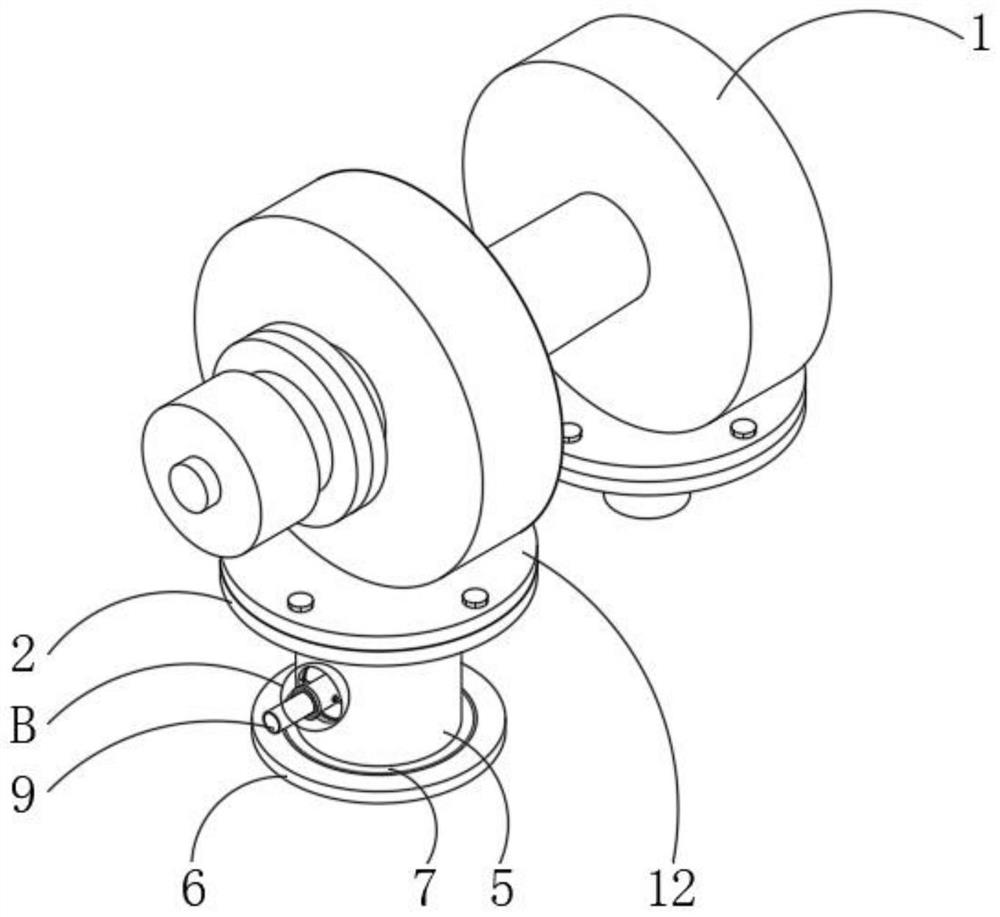
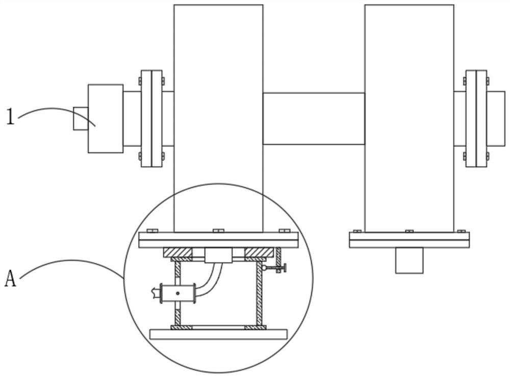
[0028] see Figure 1-6 , the present invention provides a technical solution: an oil-leakage-proof turbocharger, comprising a turbocharger body 1, a first flange 2 is provided at the bottom of one side of the turbocharger body 1, and the first method The bottom of the flange 2 is fixedly installed with a first plate body 3, and one side of the bottom of the turbocharger body 1 is fixedly installed with a second flange 12 that is compatible with the first flange 2. The first flange 2 is bolted to the second flange 12 through bolts, the intake pipe 8 communicates with the bottom of the turbocharger body 1 through the first flange 2 and the second flange 12, and the first flange 2 and The second flange 12 is used to connect and fix the first plate body 3 with the turbocharger body 1; by setting the intake pipe 8, the hose 9 communicates with the turbocharger body 1 through the intake pipe 8;

[0029] The bottom of the first plate 3 is embedded with the first turntable bearing 4,...

Embodiment 2

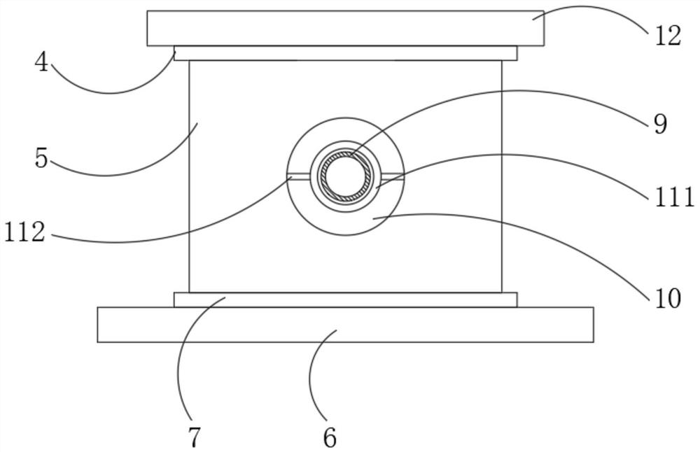
[0034] see Figure 1-6The difference between this embodiment 2 and embodiment 1 is that: the guide assembly 11 includes a tube body 111, the tube body 111 is located in the inner cavity of the through groove 10, and the centers of the front and rear sides of the tube body 111 are rotatably installed with support rods 112 , the end of the strut 112 away from the tube body 111 is slidably connected to the inner wall of the through groove 10, and the end of the hose 9 away from the intake pipe 8 slides through the tube body 111 and extends to the outside of the tube body 111; by setting the strut 112 and the chute 13. When the hose 9 shakes or moves under force, the hose 9 drives one end of the tube body 111 to tilt or droop, and the hose 9 can also drive the tube body 111 to rotate, and the tube body 111 passes through the support rod 112 in the chute 13 Rotate, so that the hose 9 is limited, and at the same time, the tube body 111 can move flexibly in a small range when it is u...


PUM


Abstract

The invention discloses an oil-leakage-proof turbocharger, which comprises a turbocharger body, a bottom of one side of the turbocharger body is provided with a first flange, and the bottom of the first flange is The first plate is fixedly installed, the bottom of the first plate is embedded with a first turntable bearing, the bottom of the first turntable bearing is fixedly installed with a sleeve, and the bottom of the sleeve is provided with a second plate , the top of the second plate body is embedded with a second turntable bearing; the present invention rotates the sleeve according to the connection angle and connection direction of one end of the hose, and the sleeve drives the pipe body in the through groove to rotate, and when the pipe body rotates to When the angle is right, turn the screw, the screw drives the ball to rotate and approach the sleeve, and the ball contacts the anti-skid pattern on the surface of the sleeve to limit the sleeve to prevent the sleeve from driving the tube to rotate at will, so as to facilitate the installation of the hose The purpose of adjusting the angle.

Description

technical field [0001] The invention relates to the technical field of turbochargers, in particular to an oil leakage-proof turbocharger. Background technique [0002] A turbocharger is actually an air compressor that compresses air to increase intake air. It uses the inertial momentum of the exhaust gas discharged from the engine to drive the turbine in the turbine chamber, and the turbine drives the coaxial impeller. The impeller presses the air sent by the air filter pipe to pressurize it into the cylinder. When the engine speed increases , the exhaust gas discharge speed and the turbine speed also increase synchronously, the impeller compresses more air into the cylinder, the pressure and density of the air increase to burn more fuel, the corresponding increase in the amount of fuel and the adjustment of the engine speed can increase the engine speed Output power, turbocharger has been popularized on many types of cars, it makes up for the inherent deficiencies of some ...

Claims


Application Information

Patent Timeline
Patent Type & Authority Patents(China)
IPC IPC(8): F02B39/00F04D29/40F04D29/00F04D29/16
CPCF02B39/00F04D29/002F04D29/161F04D29/403
Inventor 汤斌程万里陆元高孙贤锑
Owner 湖南路捷道夫涡轮增压系统有限公司
Why Eureka
Try Eureka