
Hydraulic synchronizer protection circuit and hydraulic synchronizer

A hydraulic synchronization and protection circuit technology, applied in fluid pressure actuation devices, fluid pressure actuation system testing, fluid pressure actuation system components, etc., can solve problems such as output drive imbalance, synchronization performance impact, control system cumulative deviation, etc.

Pending Publication Date: 2021-02-26
XTR SOLUTIONS
View PDF0 Cites 1 Cited by
  • Summary
  • Abstract
  • Description
  • Claims
  • Application Information

AI Technical Summary

Problems solved by technology

The hydraulic synchronization device in the prior art usually electrically connects the position sensor to the hydraulic cylinder, detects the position of the hydraulic cylinder and outputs the detected position data to the controller, and the controller can adjust the corresponding hydraulic cylinder according to the position data of each hydraulic cylinder. The hydraulic valve keeps the hydraulic cylinders driven synchronously, but the synchronous performance of such a hydraulic synchronous device is subject to the influence of the control system inside the controller. The output drive imbalance between multiple hydraulic cylinders makes the synchronization invalid. After the synchronization fails, the controller cannot detect and stop the hydraulic cylinders in time, resulting in inconsistent force and damage to the support points of the load driven by the hydraulic synchronization device.

Method used


Image

  • Hydraulic synchronizer protection circuit and hydraulic synchronizer
  • Hydraulic synchronizer protection circuit and hydraulic synchronizer
  • Hydraulic synchronizer protection circuit and hydraulic synchronizer

Examples


Embodiment Construction

[0034] Embodiments of the present invention are described in detail below, and examples of the embodiments are shown in the drawings, wherein the same or similar reference numerals denote the same or similar elements or elements having the same or similar functions throughout. The embodiments described below by referring to the figures are exemplary only for explaining the present invention and should not be construed as limiting the present invention.

[0035] In the description of the present invention, multiple means two or more than two. If the first and second are described only for the purpose of distinguishing technical features, it cannot be understood as indicating or implying relative importance or implying Indicate the number of indicated technical features or implicitly indicate the sequence of indicated technical features.

[0036]In the description of the present invention, unless otherwise clearly defined, words such as setting, installation, and connection shou...


PUM


Abstract

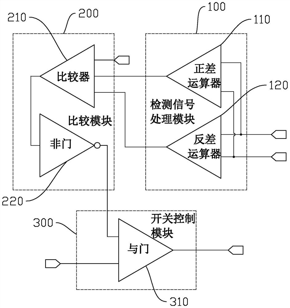
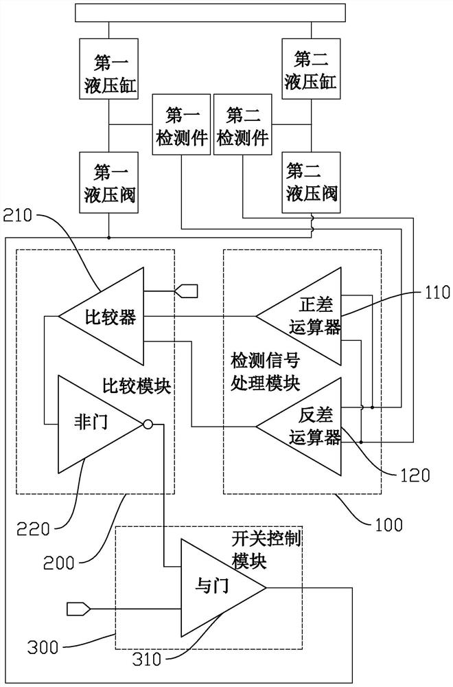
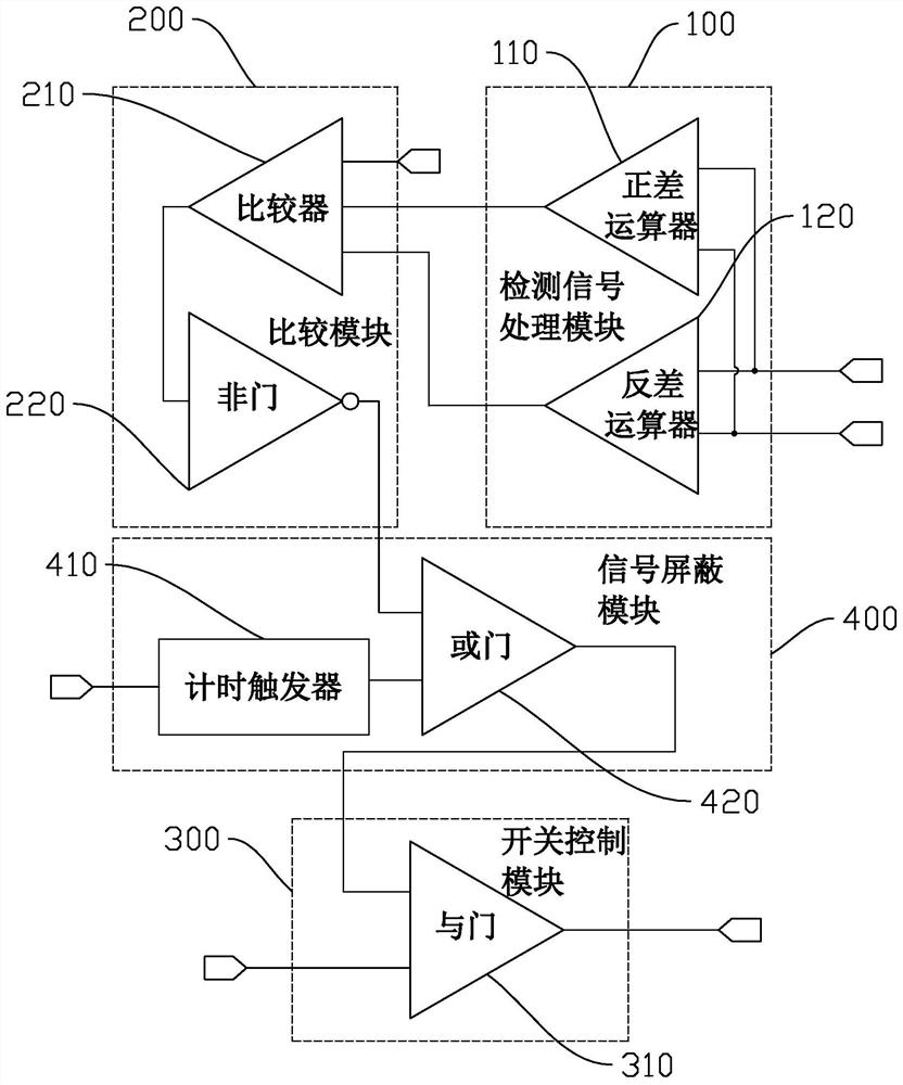
The invention discloses a hydraulic synchronizer protection circuit and a hydraulic synchronizer with the hydraulic synchronizer protection circuit. The hydraulic synchronizer protection circuit comprises a detection signal processing module, a comparison module and a switch control module. The detection signal processing module is provided with a first detection signal input end and a second detection signal input end, the comparison module is provided with a calibration value signal input end, the comparison module is electrically connected with the output end of the detection signal processing module, the switch control module is provided with an external control signal input end, the switch control module is electrically connected with the output end of the comparison module, and the switch control module outputs a switch signal of a hydraulic valve. According to the hydraulic synchronizer protection circuit, the state information of hydraulic cylinders of different paths of the hydraulic synchronizer is collected, processed and compared, when the synchronization of the hydraulic cylinders of the different paths exceeds the limit, the work of the hydraulic valve is stopped, andthe hydraulic valve is prevented from being damaged due the load driven by the hydraulic synchronizer.

Description

technical field [0001] The invention relates to the technical field of synchronizing devices, in particular to a hydraulic synchronizing device protection circuit and a hydraulic synchronizing device. Background technique [0002] The hydraulic synchronization device is often used to drive large loads or large partial loads. In the hydraulic synchronization device, multiple hydraulic valves and other components are used to control the oil intake of multiple hydraulic cylinders, which can realize simultaneous lifting / lowering of multiple hydraulic cylinders. The hydraulic synchronization device in the prior art usually electrically connects the position sensor to the hydraulic cylinder, detects the position of the hydraulic cylinder and outputs the detected position data to the controller, and the controller can adjust the corresponding hydraulic cylinder according to the position data of each hydraulic cylinder. The hydraulic valve keeps the hydraulic cylinders driven synchr...

Claims


Application Information

Patent Timeline
IPC IPC(8): F15B11/22F15B13/06F15B15/28F15B19/00F15B21/08
CPCF15B11/22F15B13/06F15B15/2838F15B19/00F15B21/087
Inventor 包晓军刘远曦李琳王育才刘会涛刘航吕刚立
Owner XTR SOLUTIONS
Learn More