Hybrid power control mechanism with three power sources

A technology of compound power and control mechanism, applied in the direction of engine components, mechanical equipment, valve operation/release devices, etc., can solve problems such as affecting product reliability and competitiveness, complex control system, and increasing maintenance costs.

Active Publication Date: 2021-02-26
CH CREATIVE CO LTD
View PDF6 Cites 0 Cited by
  • Summary
  • Abstract
  • Description
  • Claims
  • Application Information

AI Technical Summary

Problems solved by technology

[0006] However, the above combination structure has the following disadvantages in actual application: First, since each solenoid valve (or control valve) only has a single opening and closing operation action, multiple connecting pipelines are used to combine the solenoid valve (or control valve) The overall combined structure of the valve) will become more complicated, and its control system will also be more complicated. Not only the development and construction costs of the overall system structure are extremely high, but also its operation and control actions are less convenient, and the number of components also increases. The probability of damage and failure will greatly increase the maintenance cost; moreover, because the solenoid valve (or control valve) assembly installed between the power unit and the load is used for a long time, it is extremely vulnerable to external oil stains, moisture and dust. Leakage and damage caused by pollution or erosion will affect product reliability and competitiveness

Method used


Image

  • Hybrid power control mechanism with three power sources
  • Hybrid power control mechanism with three power sources
  • Hybrid power control mechanism with three power sources

Examples


Embodiment Construction

[0061] The present invention mainly utilizes the inventor of this case, and has previously proposed another invention design derived from the application number No. 108110801 "fluid transmission guiding control device and its application system" of the Taiwan invention patent application filed in China. To Chen Ming.

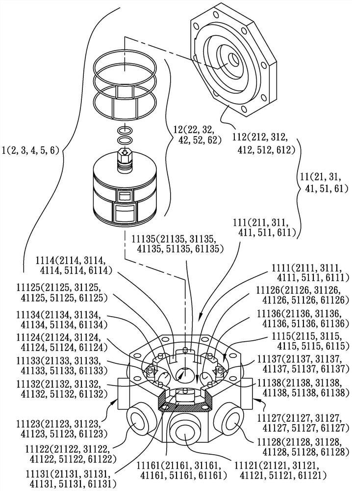
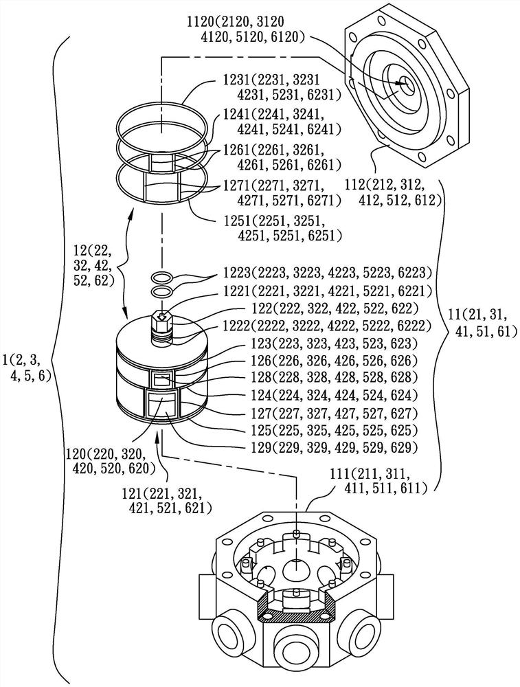
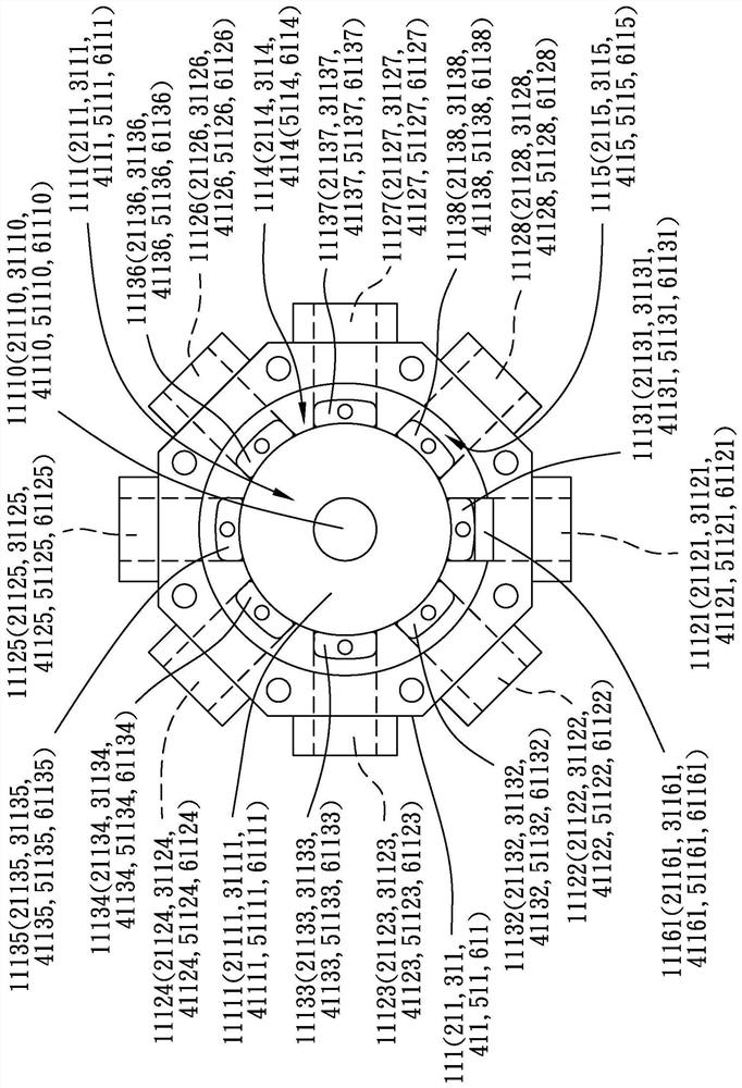
[0062] Please refer to Figure 11 , it can be seen that the overall structure of the present invention includes: a first control component 1, a second control component 2, a third control component 3, a fourth control component 4, a fifth control component 5 and a sixth control component 6; please refer to Figure 1 to Figure 11-1 As shown, each of the control assemblies 1, 2, 3, 4, 5, and 6 is composed of a power transmission and distribution unit 11, 21, 31, 41, 51, and 61 respectively combined with a switching member 12, 22, 32, and 42 , 52, 62; if the first control assembly 1 is taken as an example, it is composed of a first power transmission and distribut...


PUM


Abstract

The invention provides a hybrid power control mechanism with three power sources. The mechanism is provided with six groups of power transmission and distribution units and switching pieces matched with the six groups of power transmission and distribution units in corresponding quantity, wherein a main runner is arranged in each power transmission and distribution unit, and each main runner is respectively communicated with a plurality of branch runners; and main runners of a first power transmission and distribution unit and a second power transmission and distribution unit in the six groupsof power transmission and distribution units are respectively communicated with an output channel and an input channel of a front power device, main runners of a third power transmission and distribution unit and a fourth power transmission and distribution unit are respectively communicated with an input channel and an output channel of a middle power device, main runners of a fifth power transmission and distribution unit and a sixth power transmission and distribution unit are communicated with an output channel and an input channel of a rear power device respectively, at least part of branch runners among the power transmission and distribution units are communicated, and each switching piece is provided with a lower flow guide opening capable of being communicated with the corresponding main runner. Through simple operation, the front power device, the middle power device, the rear power device and other power devices can be controlled, and different independent or combined poweroutput effects are achieved.

Description

technical field [0001] The invention relates to a compound power control mechanism of three power sources, especially a power transmission and distribution unit controlled by a plurality of switching parts, and different flow paths are connected by preset different sub-flow channels to achieve the conversion of three power sources. The device forms a variety of independent or combined drive modes of operation for preset loads. Background technique [0002] With the reduction of global crude oil reserves and rising oil prices, countries are actively looking for other alternative energy sources and energy-saving methods to reduce the impact of the oil crisis. [0003] Currently known power sources include fuel engines (diesel, petroleum), solar power systems, electric drive systems, pressurized fluid power systems, and the like. Among the above-mentioned power sources, some power sources have better effect and excellent durability when high-speed operation is required, but th...

Claims


Application Information

Patent Timeline
Patent Type & Authority Applications(China)
IPC IPC(8): F16K11/085F16K11/22F16K31/04
CPCF16K11/0856F16K11/22F16K31/04F16K11/085
Inventor 章睿承
Owner CH CREATIVE CO LTD
Why Eureka
Try Eureka