Miniature vehicle lamp module

A module and lamp technology, applied in the field of vehicle lighting, can solve the problems of difficulty in ensuring manufacturing accuracy and positioning and installation accuracy, waste of space and cost, and low accuracy of the optical system, so as to improve the aesthetics of the appearance, reduce manufacturing costs, The effect of weakening the dispersion phenomenon

Pending Publication Date: 2021-02-26
HASCO VISION TECHNOLOGY CO LTD
1 Cites 0 Cited by

AI-Extracted Technical Summary

Problems solved by technology

However, if it is used as an auxiliary low beam module, it does not need high illuminance. It only needs to obtain a light shape with uniform illuminance and wide spread. Therefore, the volume of the light module will cause waste of space and cost.
[0005] 2. Low precision of optical system
In this car light module, the primary optical element and the radiator are positioned and installed first, and then the lens and the lens bracket are positioned and installed with the radiator or positioned and installed with the radiator through a transition bracket. T...

Method used

(1) optical system precision is high, and lens and circuit board are all directly positioned and connected with primary optical element, reduce multiple assembly errors, only need to guarantee the relative positional precision of three can guarantee optical system precision;
As shown in Figure 1, assume that the radius of curvature of lens 21 is R, the height of lens 21 is H and satisfies: H≤4R/3, this height H can be cut off by the upper and lower two ends of existing lens , only the thicker part in the middle is reserved for realization, so that the size of the lens 21 can be reduced under the premise of ensuring the light efficiency of the lens 21, so that the volume of the entire car light module is greatly reduced, forming a miniature car light module Group, beautiful in appearance, and the corresponding manufacturing cost is also greatly reduced. If the size of the optical components of the prior art lamp module is simply scaled down, the reduced lamp module has the disadvantages of unsatisfactory light shape effect, poor light effect, and failure to provide good lighting effect for the driver. This embodiment does not simply reduce the size of the lens 21 in proportion, but cuts off its upper and lower ends on the basis of the existing lens, and reduces the upper and lower height dimensions of the lens 21 under the same curvature, thereby ensuring that the lens 21 light effect, and reduce the size of the lens 21. At the same time, because the middle part of the lens 21 in this embodiment is thicker, the serious dispersion caused by the thin lens thickness is weakened, and the dispersion phenomenon can be effectively improved. In practical application, the dimensions cut off from the upper and lower ends of the existing lens can be the same, and the height of the obtained lens 21 extending from the center to the upper and lower ends is H/2. Of course, the upper and lower ends of the existing lens , The size cut off at the lower two ends can also be different. The left and right widths of the lens 21 can be longer without affecting the dispersion. Therefore, the forward projection of the lens 21 in this embodiment is a horizontal rectangle. In addition, as shown in FIG. 10 , the lens 21 in this embodiment is a biconvex lens, but of course it may also be a plano-convex lens.
As shown in Figure 1-3, the present invention provides a kind of miniature car light module, compr...

Abstract

The invention provides a miniature automobile lamp module which comprises a lens, a primary optical element and a light source which are arranged from front to back, the light source is fixed to a circuit board, a connecting part is arranged on the primary optical element, and a lens connecting part is arranged on the lens. And the primary optical element is respectively in direct positioning connection with the lens connecting part and the circuit board through the connecting part. The beneficial effects of the invention are that the optical system is high in precision, the lens and the circuit board are directly connected with the primary optical element in a positioning manner, repeated assembly errors are reduced, and the precision of the optical system can be guaranteed just through guaranteeing the relative position precision of the three parts; the structure is compact and small, the size of each optical element can be reduced, and the size of the whole automobile lamp module isreduced; the dispersion phenomenon is weakened by cutting off the upper end and the lower end of an existing lens.

Application Domain

Technology Topic

Image

  • Miniature vehicle lamp module
  • Miniature vehicle lamp module
  • Miniature vehicle lamp module

Examples

  • Experimental program(1)

Example Embodiment

[0058] The specific embodiments of the present invention will be further described in detail below with reference to the accompanying drawings. These embodiments are only used to illustrate the present invention, but not to limit the present invention.
[0059] In the description of the present invention, it should be noted that the orientation or positional relationship indicated by the terms "upper", "lower", "front", "rear", "vertical", "horizontal", etc. is based on the drawings. The orientation or positional relationship shown is only for the convenience of describing the present invention and simplifying the description, rather than indicating or implying that the indicated device or element must have a specific orientation, be constructed and operated in a specific orientation, and therefore should not be construed as a limitation of the present invention. limit. Furthermore, the terms "first", "second", and "third" are used for descriptive purposes only and should not be construed to indicate or imply relative importance.
[0060] In the description of the present invention, it should be noted that the terms "installed", "connected" and "connected" should be understood in a broad sense, unless otherwise expressly specified and limited, for example, it may be a fixed connection or a detachable connection Connection, or integral connection; can be mechanical connection, can also be electrical connection; can be directly connected, can also be indirectly connected through an intermediate medium, can be internal communication between two elements. For those of ordinary skill in the art, the specific meanings of the above terms in the present invention can be understood according to specific situations.
[0061] Also, in the description of the present invention, unless otherwise specified, "plurality" means two or more.
[0062] like figure 2 As shown, for the convenience of description, the definitions of each direction in the following embodiments are as follows: the upward direction along the drawing paper is the upward direction, the downward direction along the drawing paper is the downward direction, the rightward direction along the drawing paper is the front direction, and the downward direction along the drawing paper is the forward direction, Left is the rear direction. When describing other views, use figure 2 The determined direction serves as the basis. like Figure 11 As shown, the low beam shape of the lamp module includes the main low beam light shape A located in the central area (dotted line area) and the auxiliary low beam light shape B located in the widening area, the main low beam light shape A and the auxiliary low beam light shape B The shape B partially overlaps, the main low beam light shape A has a high illuminance, and the auxiliary low beam light shape B has a uniform illuminance, wherein the light shape refers to the light shape of the light emitted by the lamp module projected on the light distribution screen.
[0063] like Figure 1-3 As shown, the present invention provides a miniature vehicle lamp module, including a lens 21, a primary optical element 1 and a light source arranged from front to back, the light source is fixed on the circuit board 5, and the primary optical element 1 is provided with a connecting portion 10 The lens 21 is provided with a lens connecting portion 22 extending backward, and the primary optical element 1 is directly positioned and connected to the lens connecting portion 22 at the front and the circuit board 5 at the rear through the connecting portion 10 respectively. By providing the connecting portion 10 and the lens connecting portion 22 to replace the bracket in the prior art, the number of components in the lamp module can be effectively reduced, the installation accuracy between the components can be improved, the errors caused by multiple assemblies can be reduced, and the The accuracy of the optical system.
[0064] combine image 3 , 4 , 5, 8 and 9, it can be seen that, in a specific embodiment of the present invention, the lens connecting portion 22 includes upper and lower parts respectively fixed on the upper and lower ends of the lens 21, and the connecting portion 10 includes the upper and lower portions respectively corresponding to the lens connecting portion 22. The mated first connection part 11 and the second connection part 12 . The lens connecting portion 22 is provided with a plurality of positioning pins 221 facing the rear, and the first connecting portion 11 is provided with riveting holes 111 matched with the positioning pins 221, so as to connect the first connecting portion 11 and the upper portion of the lens connecting portion 22. For riveting, the second connecting portion 12 is provided with two positioning holes 121 matched with the positioning pins 221 , one of which is a circular hole and the other is a waist-shaped hole. The arrangement of the positioning pins and the positioning holes helps to further improve the installation accuracy between the lens 21 and the primary optical element 1 , and in addition, the two can be fixedly connected by means of screw connection, riveting, gluing or welding. Specifically, the lower parts of the second connecting part 12 and the lens connecting part 22 are also correspondingly provided with connecting holes 122/222, and the two are fixedly connected by a fastener 6, and the fastener 6 is preferably a mounting screw.
[0065] like figure 1 , 6 As shown in FIG. 7 , one or more positioning pins 15 are provided on the rear side of the primary optical element 1 , and positioning holes matched with the positioning pins 15 are provided on the circuit board 5 . At the same time, the connecting part 10 further includes a third connecting part 13 , the third connecting part 13 is located behind the first connecting part 11 , and a connecting hole 131 is opened on the third connecting part 13 , and the third connecting part 13 passes through the connecting hole through the fastener 6 131 is fixedly connected to the circuit board 5 .
[0066] In the specific implementation, those skilled in the art can adjust the structure and connection mode of the connecting portion 10 and the lens connecting portion 22 as required. In addition to the specific embodiment adopted in the present invention, the first connecting portion 11 and the third connecting portion 13 is combined into a connecting part, that is, the connecting part 10 only includes two parts, the upper and lower parts, and the lens 21 , the primary optical element 1 and the circuit board 5 are directly positioned and connected by fasteners.
[0067] like figure 2 and image 3 As shown, the vehicle lamp module of the present invention also includes an L-shaped radiator 4, the circuit board 5 is fixedly installed on the vertical section of the radiator 4, and the two fasteners 6 pass through the connection of the third connecting portion 13 in turn. The hole 131, the perforation on the circuit board 5 and the heat sink 4 are fixedly connected to the upper part of the three, and a threaded connection hole is also opened on the horizontal section of the heat sink 4, and another fastener 6 passes through the lens connecting part 22 in turn. The connecting hole 222 on the upper part, the connecting hole 122 on the second connecting part 12 and the threaded connecting hole on the horizontal section of the radiator 4, and the lower parts of the three are fixedly connected together by the fastener 6. Of course, those skilled in the art can also adopt other heat sinks of different shapes, and change the connection relationship accordingly.
[0068] like Figure 1-3 As shown, the lens 21 is also sleeved with a light-shielding cover 3 , and the front side of the light-shielding cover 3 is open for exposing the light-emitting surface of the lens 21 to prevent light from emitting from the side of the lens 21 . The light shield 3 is connected to the lens connecting portion 22, and can also be connected by riveting, screwing, gluing or welding.
[0069] The aforementioned primary optical element 1 is a concentrator, and at least one light source is provided on the circuit board 5, and the light source is an LED light source or a laser light source, preferably an LED light source. The vehicle lamp module can be applied to a high beam module, a main low beam module or an auxiliary low beam module. When applied to the auxiliary low-beam module, the light-emitting surface of the condenser in the prior art is generally a concave arc surface, which is adapted to the object focal plane of the lens, so that the image of the lens is clear. Figure 7 , 10 As shown in Fig. 11, the rear side of the concentrator of the present invention is provided with four condensing structures 14 corresponding to the light sources along the lateral direction, and there are only four light sources on the circuit board 5. The light beam shape B is very wide. After the pixel light spots formed by the four light sources are partially superimposed, the left and right boundaries of each pixel light spot are very clear, which will affect the uniform shape of the auxiliary low beam beam shape B. Therefore, the lamp module of the present invention The light-emitting surface of the condenser is preferably set to be flat, so as to blur the boundary of the pixel light spot and obtain a uniform auxiliary low beam light shape B.
[0070] like figure 1 As shown, assuming that the radius of curvature of the lens 21 is R, the height of the lens 21 is H and satisfies: H≤4R/3, the height H can be cut off by cutting off the upper and lower ends of the existing lens, leaving only the middle thickness Therefore, the size of the lens 21 can be reduced on the premise of ensuring the light effect of the lens 21, so that the volume of the entire lamp module is greatly reduced, and a miniature lamp module is formed. Manufacturing costs are also greatly reduced. If the size of the optical element of the vehicle lamp module in the prior art is simply reduced proportionally, the reduced vehicle lamp module has the disadvantages of unsatisfactory light shape effect, poor light efficiency, and inability to provide a good lighting effect for the driver. This embodiment does not simply reduce the size of the lens 21 proportionally, but cuts off its upper and lower ends on the basis of the existing lens, and reduces the upper and lower height dimensions of the lens 21 under the same curvature, thereby ensuring the lens 21 light effect, and reduce the size of the lens 21. At the same time, the thickness of the middle portion of the lens 21 in this embodiment is relatively thick, which weakens the serious dispersion caused by the thinness of the lens, and can effectively improve the dispersion phenomenon. In practical applications, the size of the upper and lower ends of the existing lens may be the same, and the heights of the obtained lens 21 extending from the center to the upper and lower ends are both H/2. Of course, the upper and lower ends of the existing lens are , The size of the cut off at the lower ends can also be different. The left and right widths of the lens 21 can be relatively long, which does not affect the dispersion. Therefore, the forward projection of the lens 21 in this embodiment is a horizontal rectangle. In addition, if Figure 10 As shown, the lens 21 in this embodiment is a biconvex lens, and of course it can also be a plano-convex lens.
[0071] Since the vehicle lamp module of the present invention has fewer parts and a compact structure, the size of the lens 21 can be reduced within the scope of compliance with the requirements of the regulations, so that the height is 5-15mm, the width is 15-35mm, preferably the height is 10mm, and the width is 30m. . At the same time, the thickness of the upper and lower ends of the lens 21 can be appropriately increased to weaken the dispersion phenomenon. Correspondingly, the focal length of the lens and the size of the primary optical element 1 are also greatly reduced. The focal length of the lens is 5-20 mm, preferably 10 mm, and the primary optical element 1 is about 30 mm long and 40 mm wide, so that the volume of the lamp module is greatly reduced. Small, about 80mm long, 40mm wide, and 30mm high. The lamp module of this size belongs to the miniature lamp module, which is beneficial to saving space and reducing cost. For the high beam module and the main low beam module, if a light source with high luminous flux, such as a laser light source, is used, the volume of the lamp module can also be reduced to obtain high illuminance high beam or main low beam shape A. .
[0072] To sum up, the benefits of the present invention are:
[0073] (1) The optical system has high precision. Both the lens and the circuit board are directly positioned and connected to the primary optical element to reduce multiple assembly errors. Only the relative position accuracy of the three can be guaranteed to ensure the accuracy of the optical system;
[0074] (2) The structure is compact and small, which helps to reduce the size of each optical element, reduce the volume of the entire lamp module, reduce the manufacturing cost, and has a good commercial value prospect, because the miniature lamp module is very suitable for vehicles The development trend of styling can even make the existing headlights disappear, and the lamp modules are arranged in inconspicuous positions for vehicle lighting, such as bumpers, grilles, etc., which help to further enhance the appearance of the car Spend;
[0075] (3) The upper and lower ends of the existing lens are cut off, and only the thicker part in the middle is left, which weakens the dispersion phenomenon.
[0076] The above are only the preferred embodiments of the present invention. It should be pointed out that for those skilled in the art, without departing from the technical principle of the present invention, several improvements and replacements can be made. These improvements and replacements It should also be regarded as the protection scope of the present invention.

PUM

PropertyMeasurementUnit
Height5.0 ~ 15.0mm
Focal length5.0 ~ 20.0mm
tensileMPa
Particle sizePa
strength10

Description & Claims & Application Information

We can also present the details of the Description, Claims and Application information to help users get a comprehensive understanding of the technical details of the patent, such as background art, summary of invention, brief description of drawings, description of embodiments, and other original content. On the other hand, users can also determine the specific scope of protection of the technology through the list of claims; as well as understand the changes in the life cycle of the technology with the presentation of the patent timeline. Login to view more.

Similar technology patents

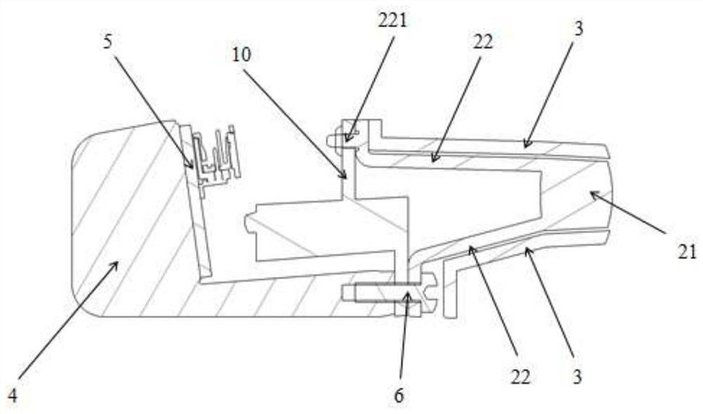
Method and device for forecasting reservoir yield

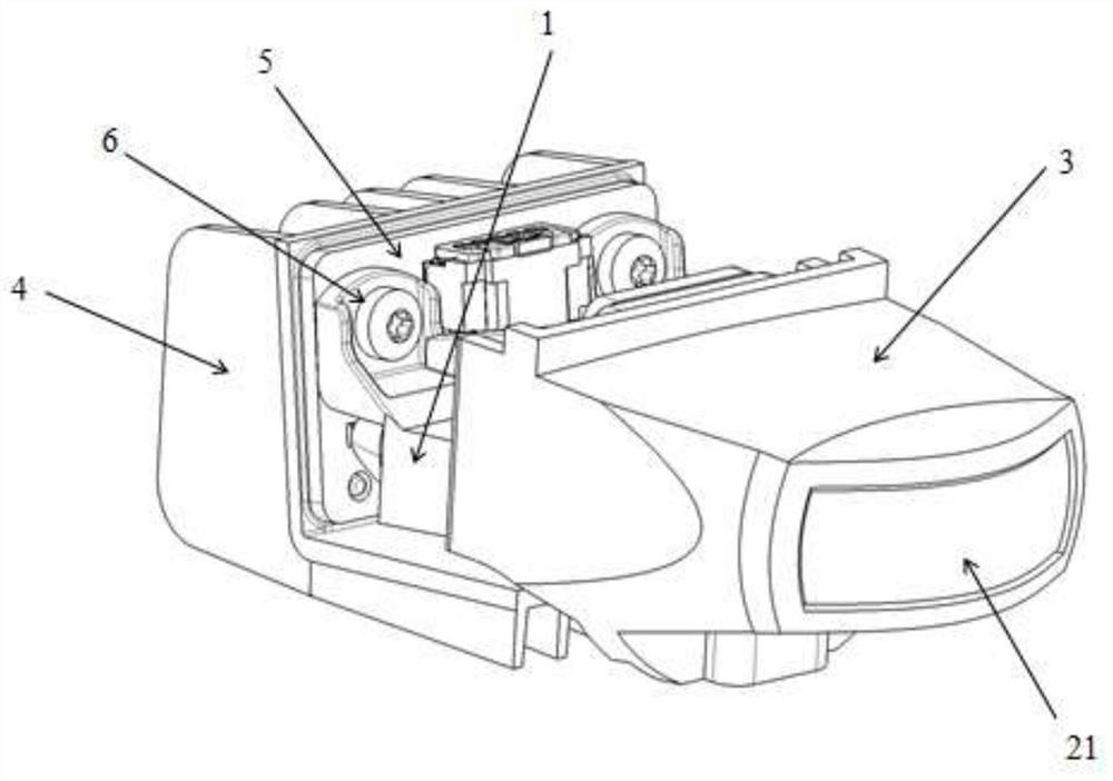
InactiveCN101906966AHigh precisionSurveyWellheadVolume factor
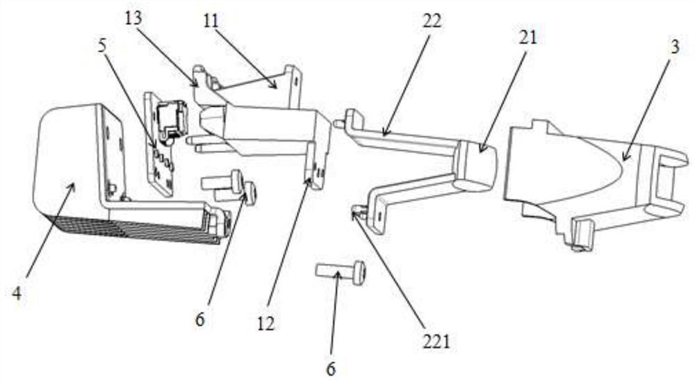
Owner:PETROCHINA CO LTD

Classification and recommendation of technical efficacy words

  • Reduce assembly errors
  • High precision

Frame structure integral air flue for multi-valve diesel engine

InactiveCN102733984AAssembly positioning is accurateReduce assembly errorsCylinder headsFoundry mouldsFlueEngineering
Owner:东风朝阳朝柴动力有限公司

High-reliability precise driving device

InactiveCN101694239AGuaranteed installation concentricityReduce assembly errorsToothed gearingsDynamo-electric gearsSelf adaptiveCam
Owner:SICHUAN UNIV +1
Why Eureka
Try Eureka