
Novel cable rack

A cable rack, a new type of technology, applied in the direction of cable laying equipment, etc., can solve the problems of cable shedding, cable skin damage, costing a lot of manpower and material resources, etc., and achieve the effect of convenient laying

Inactive Publication Date: 2021-02-26
江西利明电线电缆有限公司
View PDF0 Cites 0 Cited by
  • Summary
  • Abstract
  • Description
  • Claims
  • Application Information

AI Technical Summary

Problems solved by technology

[0004] The purpose of the present invention is to solve the existing cable rack, although it can play a basic supporting role for the cable when it is in use, when the cable is laid on the support, it is easy to cause the cable to fall off from the support, and the cable is on the support. When moving, it is easy to cause excessive friction between the cable and the bracket, which is easy to cause damage to the skin of the cable, affecting the subsequent use of the cable, and the cable is not easy to move on the bracket, resulting in the need for laying the cable. Due to the shortcomings of a large number of manpower and material resources, a new type of cable rack is proposed

Method used


Image

  • Novel cable rack
  • Novel cable rack
  • Novel cable rack

Examples


Embodiment Construction

[0040]The following will clearly and completely describe the technical solutions in the embodiments of the present invention with reference to the accompanying drawings in the embodiments of the present invention. Obviously, the described embodiments are only some, not all, embodiments of the present invention. Based on the embodiments of the present invention, all other embodiments obtained by persons of ordinary skill in the art without creative efforts fall within the protection scope of the present invention.

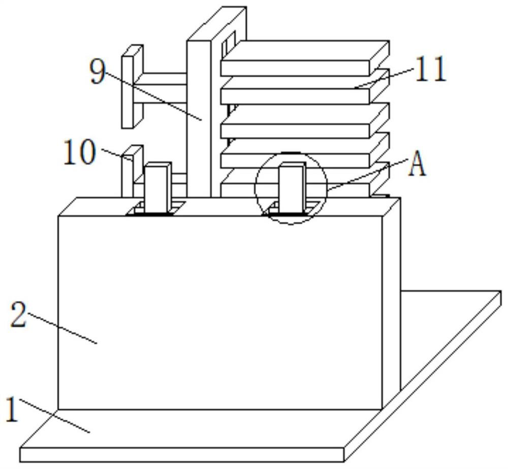
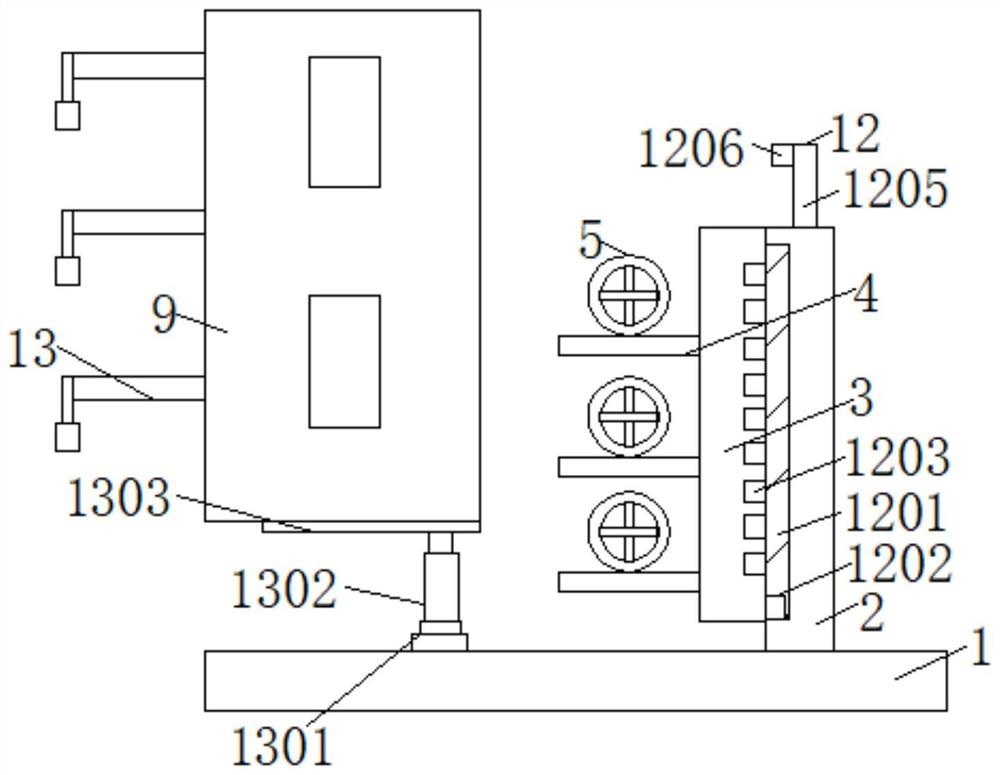
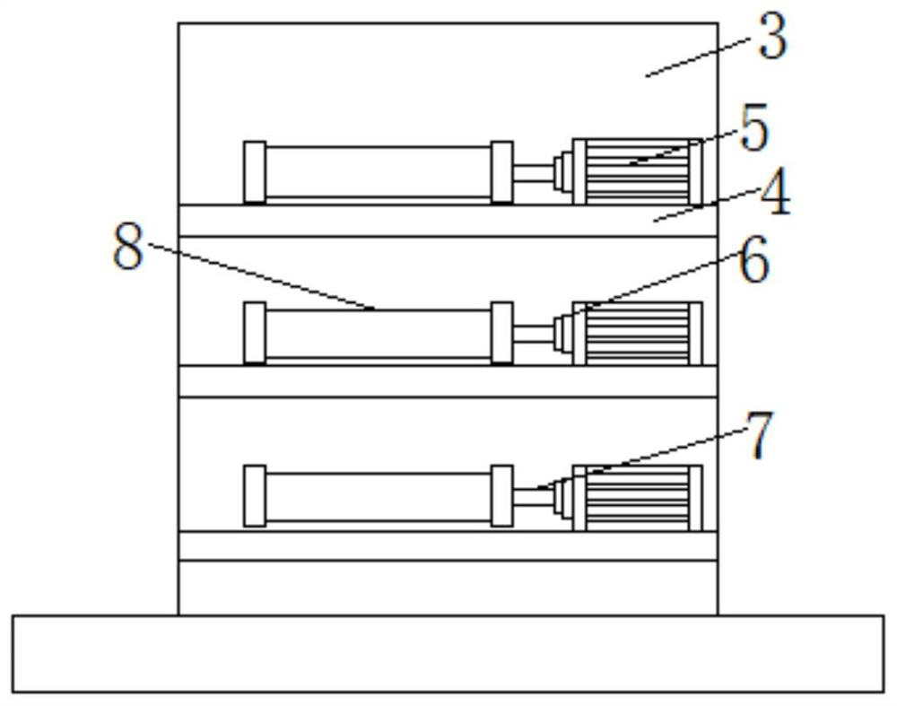
[0041] Such as Figure 1-Figure 10 As shown, a new type of cable rack includes a base 1, the top of the base 1 is fixedly connected with a first support plate 2, and one side of the first support plate 2 is connected with a second support plate 3, the second support plate 3 A plurality of bearing plates 4 are fixedly connected to one side, and a servo motor 5 is installed on the top of the bearing plate 4, and one side of the servo motor 5 is fitted with a first rot...


PUM


Abstract

The invention discloses a novel cable rack. The novel cable rack comprises a base; a first supporting plate is fixedly connected to the top end of the base; a second supporting plate is connected to one side of the first supporting plate; a plurality of bearing plates are fixedly connected to one side of the second supporting plate; a servo motor is installed at the top ends of the bearing plates;and a first rotating shaft is connected to one side of the servo motor in an embedded mode. According to the novel cable rack, through sliding of a sliding block in a sliding groove, the second supporting plate, the servo motor connected with the second supporting plate and a winding roller can be moved to a designated height conveniently, cables on the winding roller can be in butt joint with afirst groove and the a second groove conveniently, and the cables can be laid conveniently through work of the servo motor; and through overturning movement of a connecting plate on the surface of a fixing rod, a first butt joint block connected to one side of the connecting plate can be conveniently moved into a first butt joint groove, the second supporting plate, the servo motor and the windingroller can be conveniently fixed to the designated height, and cable laying is facilitated.

Description

technical field [0001] The invention belongs to the technical field of cable racks, in particular to a novel cable rack. Background technique [0002] Cables are laid in cable trenches and tunnels, and are generally fixed by brackets. Commonly used brackets include angle steel brackets and fabricated brackets. Angle steel brackets used in cable trenches have 7 different models and specifications, and the vertical distance between bracket layers is 300mm. It is used for installing 35kV cables, and 120mm is used for installing control cables. [0003] Although the existing cable rack can play a basic supporting role for the cable when it is in use, when the cable is laid on the support, it is easy to cause the cable to fall off from the support, and when the cable moves on the support, it is easy to cause the cable to be separated from the support. The friction between the brackets is too large, which can easily damage the skin of the cable and affect the subsequent use of th...

Claims


Application Information

Patent Timeline
IPC IPC(8): H02G1/06
CPCH02G1/06
Inventor 张耘
Owner 江西利明电线电缆有限公司
Learn More