
Distribution automation system line relay protection device and relay protection method

A relay protection device and power distribution automation technology, applied in the direction of emergency protection circuit devices, electrical components, etc., can solve the problems of the power distribution automation system, such as prolonged power recovery time, affecting power consumption, and large power outage areas, so as to shorten the recovery time The effect of power transmission time, reduction of economic loss, and reduction of range

Active Publication Date: 2021-02-26
晟望电气有限公司
View PDF6 Cites 0 Cited by
  • Summary
  • Abstract
  • Description
  • Claims
  • Application Information

AI Technical Summary

Problems solved by technology

The disadvantage of the relay protection action logic JD=Ka+Kc in the current distribution automation system is that when a single-phase ground fault occurs on two outgoing lines with different phases, a two-phase short-circuit fault will occur, for example, A-phase grounding occurs on outgoing line 1 , phase C of outgoing line 2 is grounded, then both outgoing line 1 and outgoing line 2 will flow zero-sequence current, that is, the logic variable Kn=1, and at the same time, the circuit breaker D1 satisfies the logic variable Ka=1 and the circuit breaker D2 satisfies the logic variable Kc=1, according to the action logic formula JD=Ka+Kc, both outgoing lines meet the action conditions, causing power outages on both lines at the same time, so the power outage area is too large, affecting power consumption, and prolonging the recovery time of the distribution automation system

Method used


Image

  • Distribution automation system line relay protection device and relay protection method
  • Distribution automation system line relay protection device and relay protection method
  • Distribution automation system line relay protection device and relay protection method

Examples


Embodiment 1

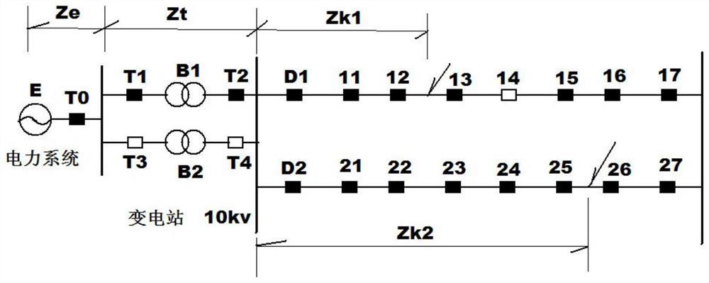
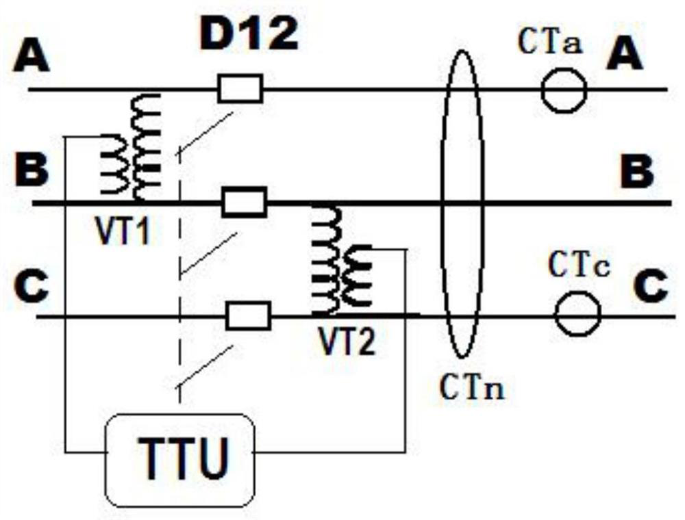
[0036] refer to Figure 1 to Figure 5 , a distribution automation system line relay protection device of the present invention, such as Figure 5 As shown, applied as Figure 1-4 The 10kv power distribution system includes an A-phase current relay, a C-phase current relay, a zero-sequence current relay and a power supply. After the moving contact La of the A-phase current relay is connected in parallel with the diode z1 series branch used to block the bypass circuit and the moving contact Lc of the C-phase current relay is connected in parallel with the diode z2 series branch used to block the bypass circuit, Then it is connected in series with the moving-off contact Lm of the zero-sequence current relay, the delay coil of the time relay ts and the power supply to form the first circuit. The moving contact La of the A-phase current relay is connected in series with the moving contact Ln of the zero-sequence current relay, the delay coil of the time relay ta and the power sup...

Embodiment 2

[0048] The difference between this embodiment and Embodiment 1 is that in this embodiment, a distribution automation system line relay protection method, the action logic formula of the outlet circuit breaker of each line of the distribution automation system is:

[0049] JD=JDs+JDa+JDc (1)

[0050] JDs=(Ka+Kc)×(1-Kn), the elapsed time Ts delay trip (2)

[0051] JDa=Ka×Kn, the elapsed time Ta delay tripping (3)

[0052] JDc=Kc×Kn, elapsed time Tc delay trip (4)

[0053] Among them, when JD=1, the corresponding outlet circuit breaker trips; when JD=0, the corresponding outlet circuit breaker remains in its original state; Ka = 1, otherwise Ka = 0; when the C-phase current Ic of the corresponding line is greater than the phase-separated fault current setting value Izd, the logic variable Kc = 1, otherwise Kc = 0; the dynamic contact Lm of the zero-sequence current relay, namely The logical inverse code of the movable contact Ln, its logical variable is represented by Km=(1-Kn...


PUM


Abstract

The invention relates to a distribution automation system line relay protection device and a relay protection method, the distribution automation system line relay protection device comprises a firstloop for controlling A-phase tripping, a second loop for controlling C-phase tripping, a third loop for controlling multi-phase fault tripping and an outlet relay control loop; and a normally closed contact of the outlet relay is connected in series into a tripping circuit of an outgoing breaker. According to the invention, on the premise that a multiphase fault occurs in an outgoing line and zero-sequence current does not exceed the standard, an A-phase or C-phase current relay is adopted to act and trip; when two outgoing lines on the same bus have single-phase earth faults of different phases, due to the fact that a delay stage difference is set between the fault action time of the phase A and the fault action time of the phase C, when an outgoing line breaker of one outgoing line actsand trips at first, the cross-line short-circuit fault between the two lines is eliminated, and the other outgoing line can continue to run in a single-phase earth mode for a period of time. The powerfailure range is reduced, the power transmission recovery time of the distribution automation system can be shortened, and the economic loss is reduced.

Description

technical field [0001] The invention relates to the technical field of relay protection for power distribution systems, in particular to a relay protection device and a relay protection method for a distribution automation system line. Background technique [0002] In the 10kv power distribution system, due to the wide power supply range, the structure of the power distribution system is set as a ring for the convenience of load sharing and adjustment, but for the convenience of fault section removal, it still operates in an open loop, such as figure 1 shown. The power system sends power to the 10kv busbar through the step-down substation. When the line fails, the two outlet circuit breakers D1 and D2 of the substation have the ability to cut off the fault current. The numbers of the section switches connected in series in line 1 are 11, 12, 13, 14, 15, 16, and 17. They are all load switches and do not have the ability to cut off the fault current of the line. Similarly, th...

Claims


Application Information

Patent Timeline
Patent Type & Authority Applications(China)
IPC IPC(8): H02H7/26
CPCH02H7/26Y04S10/20
Inventor 张旭俊姜正春
Owner 晟望电气有限公司
Learn More