Subsequent commutation failure risk assessment and suppression method for high-voltage direct-current power transmission system

A technology for commutation failure and power transmission system, applied in electrical components, power transmission AC network, etc., can solve the problems of lack of quantification, real-time commutation failure risk, AC system anti-interference ability and adjustment ability, etc., to achieve effective follow-up Commutation failure risk, assessing and suppressing subsequent commutation failure risk, effect of suppressing subsequent commutation failure

Active Publication Date: 2021-02-26
STATE GRID XINJIANG ELECTRIC POWER CO ECONOMIC TECH RES INST +1
View PDF4 Cites 0 Cited by
  • Summary
  • Abstract
  • Description
  • Claims
  • Application Information

AI Technical Summary

Problems solved by technology

In addition, as the installed capacity of new energy continues to increase, the anti-interference ability and adjustment ability of the AC system continue to decline. As a hybrid system, the "offensive" and "defensive" sides of the security and stability are in balance, which will cause subsequent commutation failures. increasingly severe impact
For the subsequent commutation failure of HVDC transmission system, domestic and foreign research mainly focuses on the analysis of influencing factors and research on suppression strategies. At present, there is a lack of indicators and suppression strategies that can quantify, real-time, and effectively evaluate the subsequent commutation failure risk in the process of system recovery.

Method used


Image

  • Subsequent commutation failure risk assessment and suppression method for high-voltage direct-current power transmission system
  • Subsequent commutation failure risk assessment and suppression method for high-voltage direct-current power transmission system
  • Subsequent commutation failure risk assessment and suppression method for high-voltage direct-current power transmission system

Examples


Embodiment Construction

[0046] The following will clearly and completely describe the technical solutions in the embodiments of the present invention with reference to the accompanying drawings in the embodiments of the present invention. Obviously, the described embodiments are only some, not all, embodiments of the present invention. Based on the embodiments of the present invention, all other embodiments obtained by persons of ordinary skill in the art without making creative efforts belong to the protection scope of the present invention.

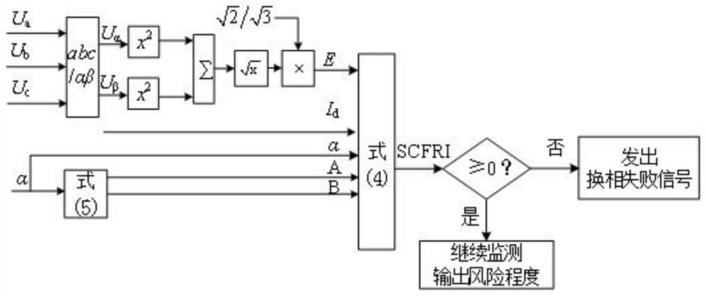
[0047] The purpose of the present invention is to provide a high-voltage direct current transmission system subsequent commutation failure risk assessment and suppression method, which considers the influence of factors such as DC current, AC voltage, and trigger angle during the fault transient period, and establishes a system subsequent commutation failure risk assessment The index realizes the discrimination and quantitative risk assessment of the subsequent...


PUM


Abstract

The invention discloses a subsequent commutation failure risk assessment and suppression method for a high-voltage direct-current power transmission system. The method comprises the steps of: obtaining a subsequent commutation failure risk assessment index SCFRI based on a commutation voltage time area analysis method; obtaining a commutation voltage effective value, direct-current current and inverter trigger angle instruction value of the high-voltage direct-current power transmission system in real time, calculating an SCFRI, and judging a subsequent commutation failure risk degree; and starting a subsequent commutation failure suppression strategy after the first commutation failure occurs, maintaining the SCFRI index of the system at the control target SCFRI0, and effectively controlling the subsequent commutation failure risk of the system, thereby suppressing the occurrence of subsequent commutation failure to the greatest extent. According to the method provided by the invention, the influence of factors such as direct current, alternating voltage and a trigger angle during a fault transient period is considered, the subsequent commutation failure risk assessment index of the system is established, and the discrimination and quantitative risk assessment of the subsequent commutation failure of the system are realized.

Description

technical field [0001] The invention relates to the technical field of operation analysis and control of a high-voltage direct current transmission system, in particular to a risk assessment and suppression method for subsequent commutation failures of a high-voltage direct current transmission system. Background technique [0002] With the continuous development of my country's economy and society, the role of the power system in the national economy is becoming more and more significant, and the supply capacity and level of the power grid are constantly improving, requiring the power grid to have higher security and reliability. Commutation failure is one of the most common fault types in HVDC technology that relies on grid voltage commutation. If the AC system fault that caused the first commutation failure is not cleared in time or improperly controlled, subsequent commutation failures may occur in the DC system during the recovery stage, which will easily cause local fa...

Claims


Application Information

Patent Timeline
Patent Type & Authority Applications(China)
IPC IPC(8): H02J3/36
CPCH02J3/36H02J2203/10Y02E60/60
Inventor 李凤婷宋新甫辛超山周专周博昊陈伟伟薛静杰李海峰高明于志勇荆世博关洪浩余中平边家瑜
Owner STATE GRID XINJIANG ELECTRIC POWER CO ECONOMIC TECH RES INST
Why Eureka
Try Eureka