Pipeline weld joint automatized ultrasound flaw detection device

An ultrasonic flaw detection and pipeline technology, which is applied in measuring devices, using sound waves/ultrasonic waves/infrasonic waves to analyze solids, and using sound waves/ultrasonic waves/infrasonic waves for material analysis, etc. Positioning and other issues to achieve the effect of reducing environmental radiation pollution, reducing labor intensity, and good development prospects

Inactive Publication Date: 2010-10-20
CHINA NAT OFFSHORE OIL CORP +2
View PDF0 Cites 2 Cited by
  • Summary
  • Abstract
  • Description
  • Claims
  • Application Information

AI Technical Summary

Problems solved by technology

[0002] At present, the widely used flaw detection method in China is still manual flaw detection, and its operation process is quite complicated. According to the shape of the weld, ultrasonic probes with different angles are required, and the position is constantly moved to ensure the incident angle and position of the ultrasonic beam. The wave form is used to judge the nature of weld defects, which is labor-intensive and low-efficiency. In many cases, it needs to rely on the experience of the operator, which is easy to cause missed and misjudgment
In recent years, some multi-channel ultrasonic flaw detection instruments have appeared. Using multi-channel ultrasonic flaw detection instruments can realize multi-beam flaw detection at the same time, but because the angle adjustment is not flexible enough (the probe model still needs to be changed), the position movement is inconvenient, and it is difficult to realize automation. Still can not meet the requirements of mass weld flaw detection
[0003] Most of the existing pipeline flaw detection devices are for flaw detection inside the pipeline, but for the ultrasonic flaw detection device for the outer surface of the pipeline, the structure of the device is complex, and it cannot be positioned well, the detection accuracy is low, and it is difficult to realize full automation.

Method used


Image

  • Pipeline weld joint automatized ultrasound flaw detection device
  • Pipeline weld joint automatized ultrasound flaw detection device
  • Pipeline weld joint automatized ultrasound flaw detection device

Examples


Embodiment Construction

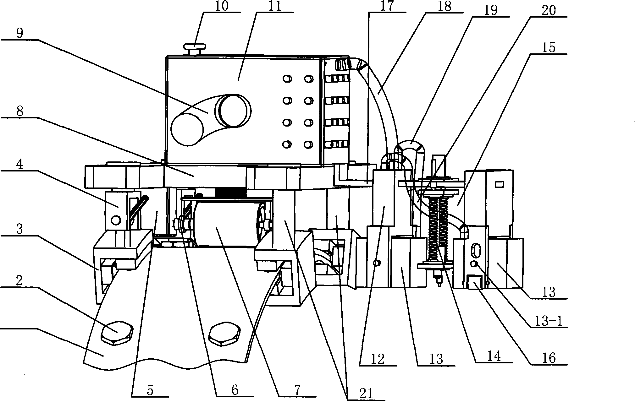
[0022] The present invention will be described in more detail below in conjunction with the accompanying drawings:

[0023] combine figure 1 , This embodiment is composed of the elastic track assembly part, the carrier trolley part, the probe scanning assembly part and the marking mechanism part; the carrier trolley is installed on the elastic track assembly, and the probe scanning assembly is fixed on the carrier trolley through the elastic plate , the marking mechanism is fixed on the elastic plate. The invention is externally connected with an ultrasonic flaw detector and an electromechanical control box. Before flaw detection, the surface of the girth weld of the pipeline and its vicinity should be derusted, polished and cooled, and a reference line should be drawn at the 12 o'clock position of the girth weld of the pipeline to supply the equipment to the equipment. The track is accurately positioned, and then the elastic track is fixed at a certain distance from the pipe...


PUM


Abstract

The invention provides an automatic ultrasonic flaw detection device for pipeline welding joints, which consists of an elastic rail assembly, a carrier trolley, a probe scanning assembly and a labeling mechanism, wherein, the carrier trolley is arranged on the elastic rail assembly, the probe scanning assembly is fixed on the carrier trolley through an elastic plate, and the labeling mechanism isfixed on the elastic plate. The device has the detection technology efficiency greatly higher than that of manual ultrasonic detection in the nondestructive detection of circumferential welding joints of pipelines, has apparent advantages of quick detection speed, environmental radiation pollution reduction, labor intensity reduction and so on, effectively reduces the misjudgment of defects, can ensure that a flaw detection image is visualized, can make real-time located, quantificational and qualitative display of the defects, inevitably hold the main advantage in the nondestructive detection of marine petroleum engineering, and have good development prospect.

Description

(1) Technical field [0001] The invention relates to an ultrasonic flaw detection device, in particular to an ultrasonic flaw detection device for pipeline welds. (2) Background technology [0002] At present, the widely used flaw detection method in China is still manual flaw detection, and its operation process is quite complicated. According to the shape of the weld, ultrasonic probes of different angles are required, and the position is constantly moved to ensure the incident angle and position of the ultrasonic beam. Waveform determines the nature of weld defects, which has high labor intensity and low detection efficiency. In recent years, some multi-channel ultrasonic flaw detection instruments have appeared. The use of multi-channel ultrasonic flaw detection instruments can realize multi-sound beam simultaneous flaw detection, but because the angle adjustment is not flexible enough (the probe model still needs to be changed), the position movement is inconvenient, and...

Claims


Application Information

Patent Timeline
Patent Type & Authority Patents(China)
IPC IPC(8): G01N29/04G01N29/265
Inventor 姜锡肇王立权赵冬岩陈东良马保家曹先伟张岚李明尤卫宏杨双羊
Owner CHINA NAT OFFSHORE OIL CORP
Why Eureka
Try Eureka