
Optical arrangement and laser system

A technology of optical devices, laser beams, applied in the direction of optics, optical components, laser welding equipment, etc.

Pending Publication Date: 2021-02-26
TRUMPF LASERSYST FOR SEMICON MFG
View PDF5 Cites 0 Cited by
  • Summary
  • Abstract
  • Description
  • Claims
  • Application Information

AI Technical Summary

Problems solved by technology

For example, unintended peaks in the intensity curve or excessively steep sides of the intensity profile can have an adverse effect on the recrystallization of the semiconductor surface, or can lead to thermal stress

Method used


Image

  • Optical arrangement and laser system
  • Optical arrangement and laser system
  • Optical arrangement and laser system

Examples


Embodiment Construction

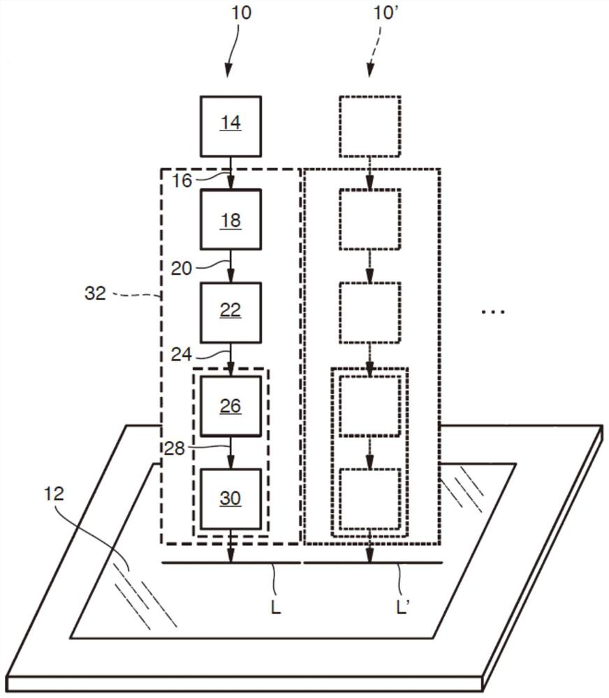
[0044] figure 1 is a schematic illustration of a laser system 10 for generating radiation with an intensity distribution L having a linear beam cross-section in the treatment plane 12 .

[0045] The laser system 10 includes at least one laser light source 14 for emitting laser radiation 16 . The laser light source 14 is preferably designed as a multimode laser. Laser radiation 16 optionally feeds an input laser beam 20 via a preshaping optical unit 18 . The preshaping optics unit 18 can, for example, have a collimating effect and / or shape the laser radiation 16 into an input laser beam 20 with an elliptical beam cross section.

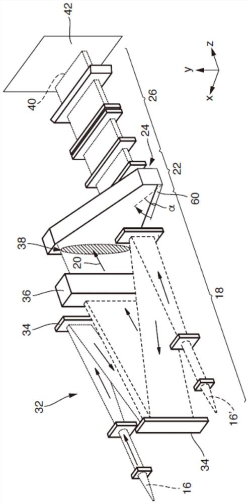
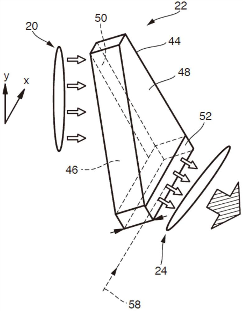
[0046] The input laser beam 20 is guided through a shaping optics unit 22 and emerges therefrom as a beam package 24 . The beam package 24 is converted into an output beam 28 by means of a homogenizing optical unit 26, as will be explained in more detail below. The output beam 28 can optionally be transformed into an intensity distribution L by mea...


PUM


Abstract

The invention relates to an optical arrangement (32) for converting an input laser beam (20) into a line-like output beam (28, 40), the optical system (32) comprising: - a reshaping optical unit (22)comprising an input aperture (50) and an output aperture (52) with an elongate extent, said output aperture extending an elongate fashion along an aperture longitudinal direction (58), - a homogenization optical unit (26), which is embodied to convert the beam packet (24) emerging from the reshaping optical unit (22) into the line-like output beam (40). With respect to the direction of the line (x), the aperture longitudinal direction (58) extends in a manner rotated about the direction of propagation (z) by a non-vanishing angle of rotation (alpha). The invention also relates to a laser system for generating a line-shaped intensity distribution.

Description

technical field [0001] Optical arrangements for inputting a laser beam into a linear output beam are described, as well as laser systems including such optical arrangements. Background technique [0002] The mentioned laser systems are used in particular for generating high-intensity radiation with an intensity distribution having a beam cross section extending in a linear manner. In the following, the axis defined by the linear extension is referred to as the "major axis" of the intensity distribution. The axis perpendicular to the direction of the line and perpendicular to the direction of propagation is also called the "short axis". For the purpose of describing the geometric relationship, the major axis (x), minor axis (y) and direction of propagation (z) shall define an oriented right-handed Cartesian coordinate system. [0003] Such beam profiles are used, for example, for the treatment of glass or semiconductor surfaces (eg tempering, annealing). For this, the line...

Claims


Application Information

Patent Timeline
IPC IPC(8): G02B17/00B23K26/064G02B27/09G02B27/14
CPCG02B27/0927G02B27/0972G02B27/0988G02B17/006G02B27/145B23K26/0608B23K26/0643B23K26/0648B23K26/0738
Inventor 托尔斯滕·贝克丹尼尔·弗拉姆安德里亚斯·海梅斯朱利安·赫尔斯特恩克里斯蒂安·林格尔费力克斯·马歇尔西尔克·蒂尔费尔德克里斯托夫·蒂尔科恩
Owner TRUMPF LASERSYST FOR SEMICON MFG
Features
  • Generate Ideas
  • Intellectual Property
  • Life Sciences
  • Materials
  • Tech Scout
  • Unparalleled Data Quality
  • Higher Quality Content
  • 60% Fewer Hallucinations
Learn More