Stirring device for food detection
A technology for stirring device and food detection, which is applied to mixers with rotating stirring devices, preparation of samples for testing, testing of food, etc., can solve the problem of inability to adjust the rotation speed of a stirring rod, affecting the stirring effect of food samples, and insufficient stirring of food. Complete and other problems to achieve the effect of improving the stirring effect
- Summary
- Abstract
- Description
- Claims
- Application Information
AI Technical Summary
Problems solved by technology
Method used
Image
Examples
Embodiment 1
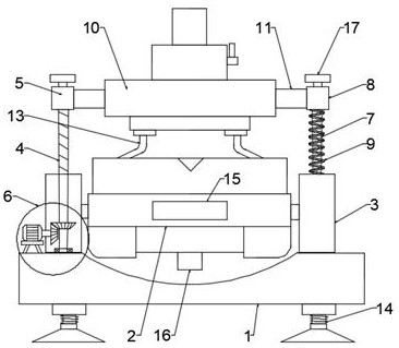
[0020] see figure 1 , in an embodiment of the present invention, a stirring device for food detection, including a base 1, a reaction pool 2 is arranged above the base 1, and support columns 3 are symmetrically arranged on both sides of the base 1, and one side supports A threaded rod 4 is arranged above the column 3, and a lifting seat 5 is threadedly connected to the threaded rod 4. A lifting device 6 is arranged inside the supporting column 3, and a sliding device is fixedly installed above the supporting column 3 on the other side above the base 1. Rod 7, on which sliding rod 7 is slidably connected with sliding seat 8, between said sliding seat 8 and the top of support column 3, a compression spring 9 is fixedly connected, and a top cover 10 is arranged above said reaction pool 2, said top Both sides of the cover 10 are respectively fixedly connected with the lifting seat 5 and the sliding seat 8 through the fixed rods 11. The inside of the top cover 10 is provided with a...
Embodiment 2
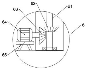
[0023] see figure 2 , in this embodiment, the lifting device 6 includes a rotating rod 61, the rotating rod 61 is fixedly connected with the threaded rod 4, the bottom of the rotating rod 61 is equipped with a driven bevel gear 62, and the driven bevel gear 62 One side is meshed with a driving bevel gear 63, the driving bevel gear 63 is connected to the output end of the rotating motor 64, and a fixed seat 65 is arranged below the rotating motor 64, and when the food is stirred, the rotating motor 64 drives the The bevel gear 63 meshes with the driven bevel gear 62, which drives the rotating rod 61 and the threaded rod 4 to rotate, so that the lifting seat 5 moves downwards, and the reaction tank 2 is closed, which improves the sealing effect of the reaction tank 2 during stirring.
[0024] In this embodiment, the ends of the threaded rod 4 and the sliding rod 7 are fixedly installed with a limiting plate 17 .
Embodiment 3
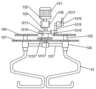
[0026] see image 3 , in this embodiment, the driving device 12 includes a driving motor 121, a first rotating shaft 122 is connected below the driving motor 121, and a cross bar 123 is fixedly connected to the bottom of the first rotating shaft 122, and the cross bar Limiting sleeves 124 are installed symmetrically at both ends of 123, and a second rotating shaft 125 is slidably engaged in the limiting sleeve 124. A first driven gear 126 is installed above the second rotating shaft 125. The first driven gear 126 A second driven gear 127 is installed above the driven gear 126; a mounting seat 128 is arranged outside the first rotating shaft 122, and a sliding tube 129 is fixedly connected to the bottom of the mounting seat 128, and a slide card is mounted on the sliding tube 129. An adjustment sleeve 1210 is connected, an adjustment block 1211 is arranged above the adjustment sleeve 1210, a first fixed gear 1212 is arranged below the adjustment sleeve 1210, and a second fixed ...
PUM
 Abstract
Description
Claims
Application Information
 - R&D
- Intellectual Property
- Life Sciences
- Materials
- Tech Scout
- Unparalleled Data Quality
- Higher Quality Content
- 60% Fewer Hallucinations
Browse by: Latest US Patents, China's latest patents, Technical Efficacy Thesaurus, Application Domain, Technology Topic, Popular Technical Reports.
© 2025 PatSnap. All rights reserved.Legal|Privacy policy|Modern Slavery Act Transparency Statement|Sitemap|About US| Contact US: help@patsnap.com


