
Motor driving device for driving revolution and rotation of eccentric cutterhead

A motor-driven, cutter head technology, applied in the direction of electromechanical devices, electric components, electrical components, etc., can solve the problems of single cross-sectional shape and single mode.

Pending Publication Date: 2021-08-10
SHANGHAI TUNNEL ENG CO LTD +1
View PDF0 Cites 0 Cited by
  • Summary
  • Abstract
  • Description
  • Claims
  • Application Information

AI Technical Summary

Problems solved by technology

[0002] Most traditional machinery (such as roadheaders) have a single drive mode for the cutter head, and most of them are driven by a group of motors to drive the center turntable to rotate and then drive the output shaft and the cutter head to rotate. Under the action of the gear system, the rotation at a specific speed is realized. Since the revolution speed and rotation speed of the output shaft are relatively fixed in this method, the output shaft is driven by the traditional method, and the cutting section shape is relatively simple, and only a single section shape can be completed. construction

Method used


Image

  • Motor driving device for driving revolution and rotation of eccentric cutterhead
  • Motor driving device for driving revolution and rotation of eccentric cutterhead
  • Motor driving device for driving revolution and rotation of eccentric cutterhead

Examples


Embodiment Construction

[0017] In order to solve the problem that the revolution speed and rotation speed of the output shaft are relatively fixed and the shape of the cutting section is single in the traditional cutter head drive mode, the present invention provides a motor drive device for driving the revolution and rotation of the eccentric cutter head, which can respectively realize the output The free adjustment of the rotation speed and revolution speed of the shaft, combined with the rotation of the cutterhead itself, can realize cutting of different cross-sectional shapes on the same machine.

[0018] The motor drive device for driving the revolution and rotation of the eccentric cutter head will be further described below with reference to the accompanying drawings in specific embodiments.

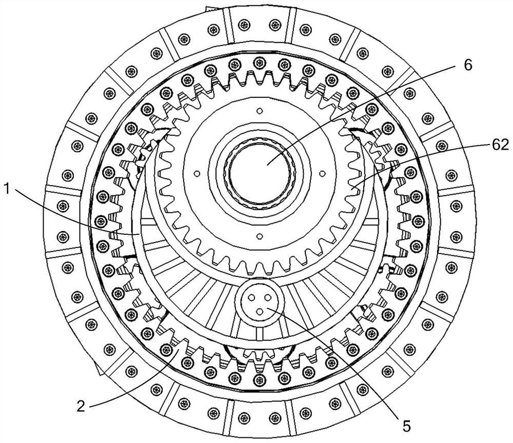
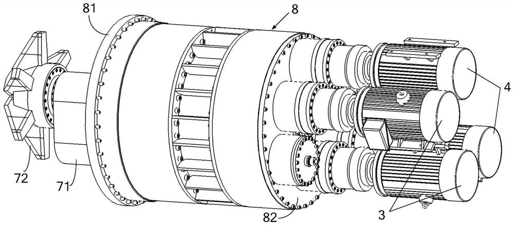
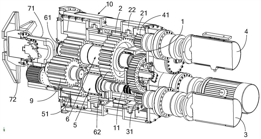
[0019] refer to Figure 1 ~ Figure 3 , figure 1 A schematic diagram showing the positional relationship of the central turntable, the first gear ring, the input shaft, the output shaft and the planetary...


PUM


Abstract

The invention relates to a motor driving device for driving revolution and rotation of an eccentric cutterhead. The motor driving device comprises a central rotating disc, a first gear ring coaxially arranged with the central rotating disc, a first motor for driving the central rotating disc to rotate, a second motor for driving the first gear ring to rotate, and an output shaft and an input shaft which are rotationally connected to the central rotating disc, wherein the output shaft and the input shaft are parallel to each other and deviate from the axis of the central rotating disc; the output shaft is sleeved with a driven gear, and the input shaft is sleeved with a driving gear meshed with the driven gear and a planetary gear rotating around the axis of the first gear ring along with rotation of the central rotating disc; the eccentric cutterhead comprises an eccentric connecting sleeve and a cutterhead, wherein a first mounting cylinder and a second mounting cylinder are arranged on the eccentric connecting sleeve in the radial direction of the central rotating disc, and the cutterhead is rotationally connected to the first mounting cylinder; and the output shaft is fixedly connected to the second mounting cylinder. The rotation speed and the revolution speed of the output shaft can be freely adjusted respectively, and cutting of different section shapes on the same machine can be achieved.

Description

technical field [0001] The invention relates to the field of tunnel construction equipment, in particular to a motor drive device for driving an eccentric cutterhead to revolve and rotate. Background technique [0002] Most traditional machines (such as roadheaders) have a single drive mode for the cutter head, and most of them are driven by a group of motors to drive the center turntable to rotate and then drive the output shaft and the cutter head to rotate. Under the action of the gear system, the rotation at a specific speed is realized. Since the revolution speed and rotation speed of the output shaft are relatively fixed in this method, the output shaft is driven by the traditional method, and the cutting section shape is relatively simple, and only a single section shape can be completed. construction. Contents of the invention [0003] In order to solve the above problems, the present invention provides a motor drive device for driving the revolution and rotation ...

Claims


Application Information

Patent Timeline
Patent Type & Authority Applications(China)
IPC IPC(8): E21D9/10E21D9/11H02K7/116
CPCE21D9/1086E21D9/112H02K7/116
Inventor 庄欠伟杨正黄志红翟一欣彭世宝袁玮皓李炎龙张弛孙骏蒋宏亮颜洪宇吴兆宇徐天明陈琦
Owner SHANGHAI TUNNEL ENG CO LTD
Learn More