

Rotary wood spoon polishing device
A rotary, wooden spoon technology, used in grinding drives, grinding machines, grinding racks, etc., can solve problems such as low efficiency and achieve the effect of rapid grinding
- Summary
- Abstract
- Description
- Claims
- Application Information
AI Technical Summary
Problems solved by technology
Method used
Image

Examples
Embodiment 1
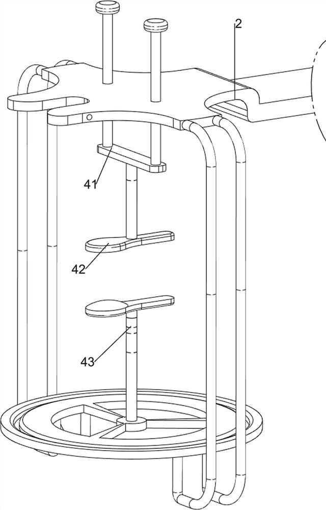
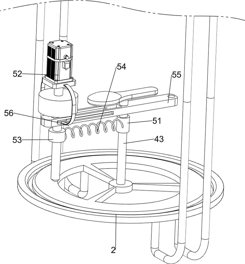
[0058] A rotary wooden spoon grinding device, such as figure 1 , figure 2 , image 3 , Figure 4 , Figure 5 , Figure 6 and Figure 7 As shown, it includes a base 1, a first support frame 2, a cylinder 3, a clamping mechanism 4 and a frosting mechanism 5. The base 1 is provided with a first support frame 2, and the lower part of the front side of the first support frame 2 is provided with a cylinder 3. A clamping mechanism 4 is provided on the first support frame 2 , and a sanding mechanism 5 is provided on the base 1 .
[0059] When the wooden spoon needs to be polished, put the wooden spoon on the clamping mechanism 4, squeeze the clamping mechanism 4 to clamp the wooden spoon, open the sanding mechanism 5, and after the sanding mechanism 5 has polished the edge of the wooden spoon, close the sanding mechanism 5. Open the clamping mechanism 4 and take out the polished wooden spoon.
[0060] The clamping mechanism 4 includes a first connecting rod 41, a first pressin...
Embodiment 2
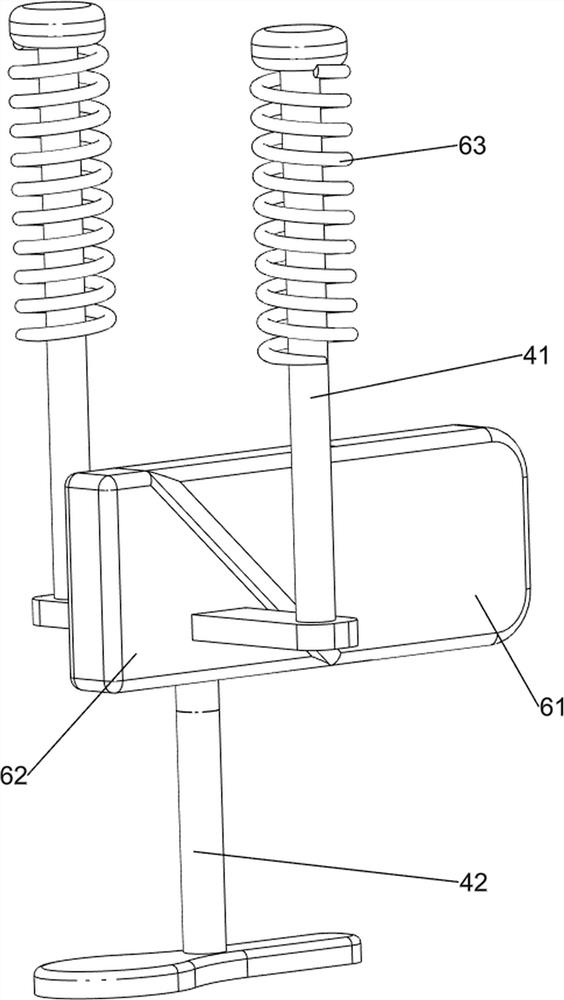
[0065] On the basis of Example 1, such as figure 1 , Figure 4 , Figure 5 , Figure 6 and Figure 7 As shown, an auxiliary clamping mechanism 6 is also included, and the auxiliary clamping mechanism 6 includes a first wedge block 61, a second wedge block 62 and a second spring 63, and the output shaft of the cylinder 3 is connected with the first wedge block 61, A second wedge block 62 is disposed on the top of the first pressing block 42 , the rear side of the first wedge block 61 is in contact with the front side of the second wedge block 62 , and a second spring 63 is sleeved on the top of the first connecting rod 41 .
[0066] Open the cylinder 3, the output shaft of the cylinder 3 drives the first wedge block 61 to move, thereby driving the second wedge block 62 to move downward, and then drives the first connecting rod 41 to move downward, the second spring 63 is squeezed, and the first connection The downward movement of the rod 41 drives the first pressing block 4...
PUM
 Abstract
Description
Claims
Application Information