
Composite connection type hydraulic knife handle

A composite connection and tool holder technology, applied in the field of composite connection hydraulic tool holders, can solve the problems of restricting the use of the tool holder, affecting the sealing performance of the hydraulic passage, replacing and maintaining the main body of the tool holder and the inner tank separately, and improving the overall performance. Strength, avoidance of extravasation effect

Pending Publication Date: 2018-11-30
成都成林数控刀具股份有限公司
View PDF0 Cites 1 Cited by
  • Summary
  • Abstract
  • Description
  • Claims
  • Application Information

AI Technical Summary

Problems solved by technology

[0004] Practice has proved that the existing hydraulic tool holders also have many defects during use, mainly including the following aspects: ①The main body of the tool holder and the inner tank connected by a single sealing ring sealing method, under the high-pressure expansion state, the oil chamber The oil medium will leak from the contact surface between the cavity of the main body of the handle and the outer circle of the inner tank, which limits the use of the handle under extreme high pressure; ②The main body of the handle and the inner tank connected by welding, usually The quality requirements for welding are extremely high, the operating space at the bottom of the hole is narrow, the welding is difficult, and the reliability of welding cannot be effectively guaranteed, and the hard welding method is usually used. Separate replacement and maintenance increases the cost of use; ③The internal clearance and smoothness of the piston rod and piston sleeve assembled in the existing hydraulic tool holder will change after long-term frictional contact, which affects the smoothness of the entire hydraulic channel. Sealing, reducing the pressure bearing capacity of hydraulic tool holders

Method used


Image

  • Composite connection type hydraulic knife handle
  • Composite connection type hydraulic knife handle
  • Composite connection type hydraulic knife handle

Examples


Embodiment Construction

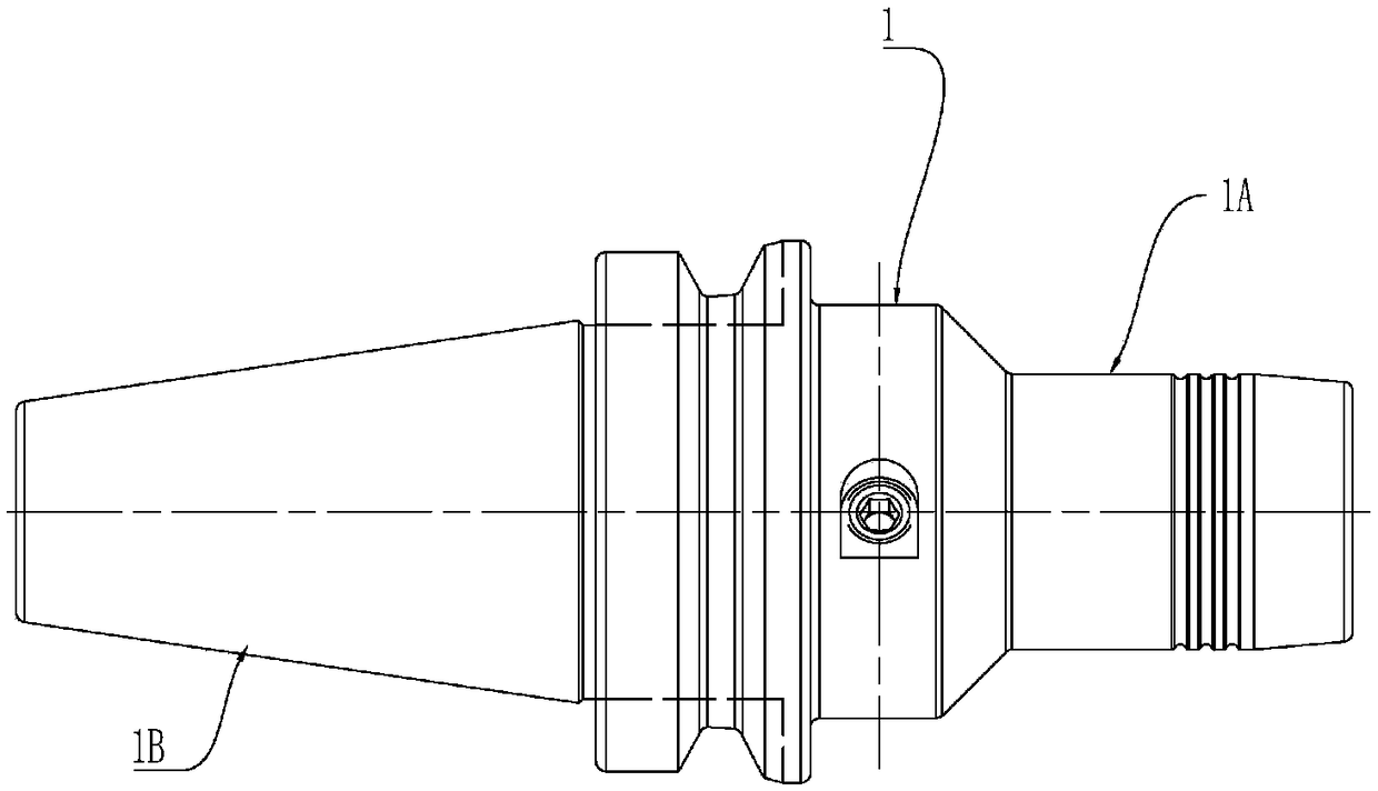
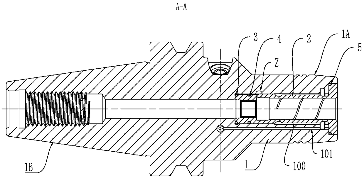
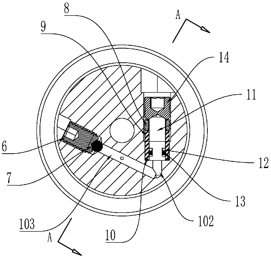
[0043] See attached figure 1 , figure 2 , image 3 , Figure 4 , Figure 5 , Figure 6 , Figure 7 and Figure 8 The present invention is further described.

[0044] The invention relates to a composite connection hydraulic knife handle, which comprises a knife handle main body (1) and an elastic thin-walled inner ring (2) arranged inside the knife handle main body (1), the knife handle main body (1) and the elastic thin-walled inner ring (2). A hydraulic oil chamber (100) is arranged between the inner rings (2); the tool handle main body (1) is also provided with a hydraulic oil injection and discharge hole (103), a pressure hole (102), and a The hydraulic oil diversion hole (101) connected to the oil filling hole (103) and the pressure hole (102) is connected with the hydraulic oil chamber (100); a hydraulic passage is set on the top of the pressure hole (102); the hydraulic pressure The channel is assembled with a piston rod (11), a piston sleeve (9), and a pressur...


PUM


Abstract

The invention relates to a composite connection type hydraulic knife handle. The composite connection type hydraulic knife handle comprises a main knife handle body and an elastic thin-wall inner ringarranged in the main knife handle body, wherein a hydraulic oil cavity is arranged between the main knife handle body and the elastic thin-wall inner ring; the elastic thin-wall inner ring is arranged as a barrel thin-wall structure with two thick ends and a thin middle part; and the side outer rings of the two ends of the elastic thin-wall inner ring make contact with the support surfaces of inner holes of the main knife handle body. The main knife handle body and the elastic thin-wall inner ring are fixed in a manner of combining brazed connection and interference fit connection, the effectof stress on the connection performance of the main knife handle body and the elastic thin-wall inner ring is reduced, the joint of the main knife handle body and the elastic thin-wall inner ring isprevented from tear under the high pressure state, and therefore the service life of the hydraulic knife handle is prolonged. Meanwhile, by improving the structure of a piston rod and the structure ofa piston sleeve, the piston sleeve is quickly maintained, the overall sealing performance of a hydraulic access is improved, and the overall strength of the hydraulic knife handle is improved.

Description

technical field [0001] The invention relates to the technical field of numerical control tool production, in particular to a composite connection hydraulic tool holder. Background technique [0002] Compared with various types of rigid tool holders such as spring sleeve type, shrink-fit type, side-fixed type, and tapered needle roller pressing type, hydraulic tool holders are flexible and fixed, and when the tool holder vibrates, the tool The damage can be greatly reduced, and it has been widely used in modern CNC machining equipment. [0003] The working principle of the hydraulic tool holder is: by setting the oil cavity inside the hydraulic tool handle, the oil cavity is formed by the cavity with the oil groove on the main body of the tool handle and the outer circle with the groove on the inner tank, and the oil cavity on the main body of the tool handle The oil passage is connected with the oil tank, and the other end of the oil passage is provided with a pressure bolt...

Claims


Application Information

Patent Timeline
IPC IPC(8): B23Q3/00
CPCB23Q3/00
Inventor 李浩翰张娟顾兴文倪刚
Owner 成都成林数控刀具股份有限公司
Learn More