Flying life buoy

A lifebuoy and shell technology, applied in the field of flying lifebuoy, can solve the problems of high cost of helicopter rescue, limited distance, and long preparation time for lifebuoy, so as to reduce physical consumption, improve rescue success rate, and improve rescue efficiency.

Pending Publication Date: 2021-03-02
NANJING KAITIANYAN UAV TECH CO LTD
View PDF1 Cites 5 Cited by
  • Summary
  • Abstract
  • Description
  • Claims
  • Application Information

AI Technical Summary

Problems solved by technology

[0005] The present invention aims at the deficiencies in the above-mentioned prior art, such as the high cost of helicopter rescue, the long preparation time for carrying the lifebuoy on the UAV, and the limited sea conditions and distances of the lifeboat on the surface, etc., and provides a flying lifebuoy with quick response and high rescue efficiency

Method used


Image

  • Flying life buoy
  • Flying life buoy
  • Flying life buoy

Examples


Embodiment Construction

[0025] The present invention is described in further detail now in conjunction with accompanying drawing. These drawings are all simplified schematic diagrams, which only illustrate the basic structure of the present invention in a schematic manner, so they only show the configurations related to the present invention.

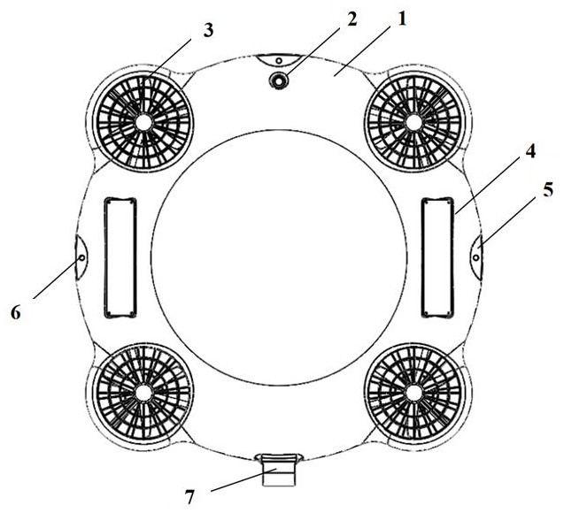
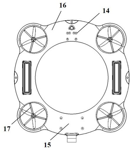
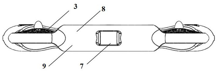
[0026] The figure includes the following structures: shell 1, switch 2, protective grille 3, battery compartment 4, tether hole platform 5, tether hole 6, observation compartment 7, upper shell 8, lower shell 9, through hole 10, paddle 11. Motor 12, underwater thruster 13, electric regulator 14, control system 15, foam floating body 16, tripod 17.

[0027] Such as figure 1 As shown, a flying buoy includes a main body of the buoy. The main body of the buoy includes a shell and a foam floating body filled inside the shell. The shell is made of plastic. The main body of the buoy is also equipped with two battery compartments, a control system and a flight power ...


PUM


Abstract

The invention discloses a flying life buoy which comprises a life buoy main body, the life buoy main body comprises a shell and a foam floating body filled in the shell, a power supply, a control system and a flying power system are further arranged on the life buoy main body, the power supply supplies power to the control system and the flying power system, and the control system controls the flying power system to be started or stopped. The flight power system comprises at least two sets of flight assemblies, each flight assembly comprises an electronic speed controller, a brushless motor and a propeller, through holes are equidistantly or symmetrically preset in the shell, the diameter of each through hole is larger than the width of the shell ring, and the shell at the outer edge of each through hole protrudes outwards in the radial direction of the shell. Compared with the prior art, the flying life buoy has the beneficial effects that the flying life buoy can be quickly sent to the side of a person falling into water through the control system and the flying power system, and the rescue efficiency is improved; a rescuer does not need to go into water for rescue, and the safety of the rescuer is guaranteed.

Description

technical field [0001] The invention belongs to the technical field of water lifesaving equipment and relates to a flying lifebuoy. Background technique [0002] With the improvement of our country's development of water areas or sea areas, the frequency of people's sea activities has gradually increased, resulting in frequent drowning accidents. The existing methods of throwing life buoys are all manual throwing, which is difficult to throw accurately, and there are many areas that need rescue on water that cannot be reached artificially, and rescue cannot be carried out in time. The cost of rescue by helicopter is high, and the maneuverability is poor. [0003] With the development of science and technology, due to the advantages of low cost of use, fast flight speed and short preparation time, drones have begun to be applied in various industries. In view of the need for rapid response to water rescue, UAVs with quick response and strong maneuverability have been widely ...

Claims


Application Information

Patent Timeline
Patent Type & Authority Applications(China)
IPC IPC(8): B63C9/00B60F5/02B64C39/02
CPCB63C9/00B60F5/02B64C39/024B64U10/13B64U30/20B64U2101/00B64U50/19B64U2201/20
Inventor 陈冲石晓雨张彪
Owner NANJING KAITIANYAN UAV TECH CO LTD
Why Eureka
Try Eureka