Anti-blocking raw material unloading system
A raw material, anti-blocking technology, applied in packaging, sustainable manufacturing/processing, climate sustainability, etc., can solve problems such as easy blockage of discharge ports
- Summary
- Abstract
- Description
- Claims
- Application Information
AI Technical Summary
Problems solved by technology
Method used
Image
Examples
Embodiment 1
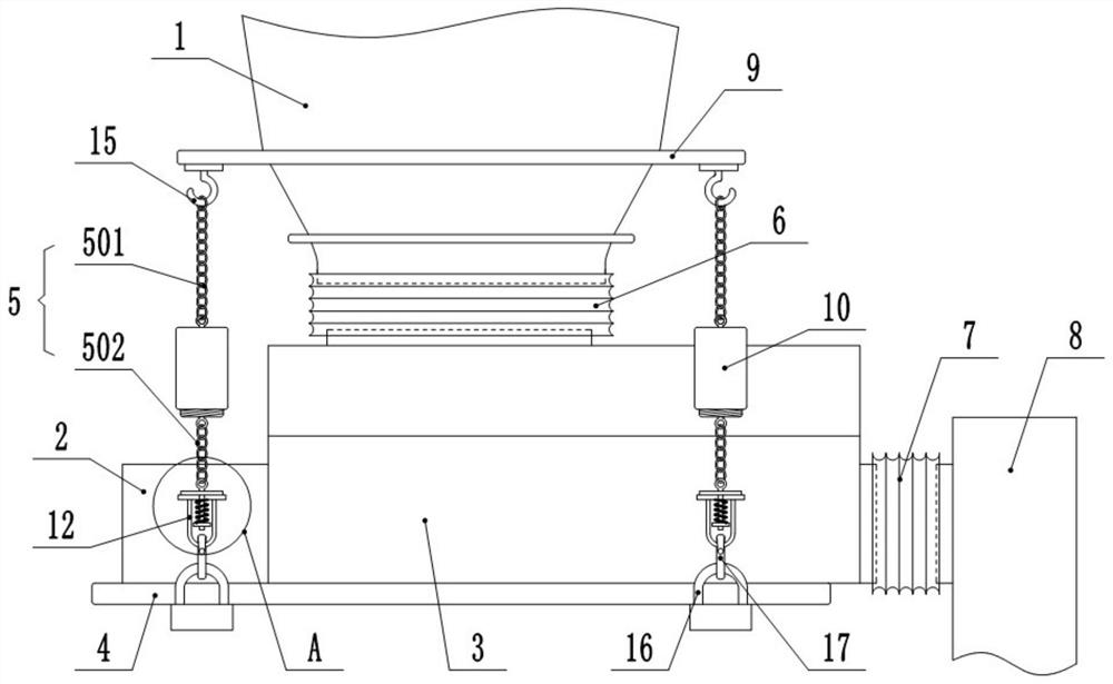
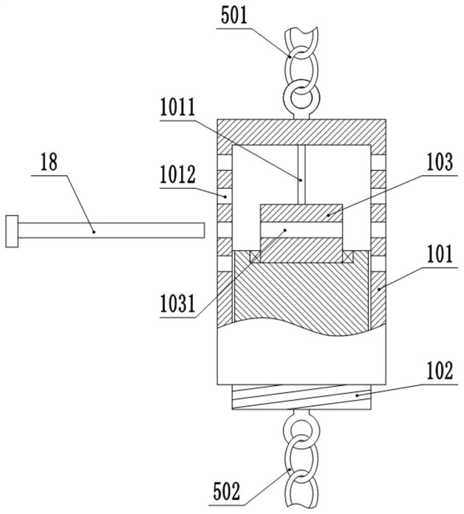
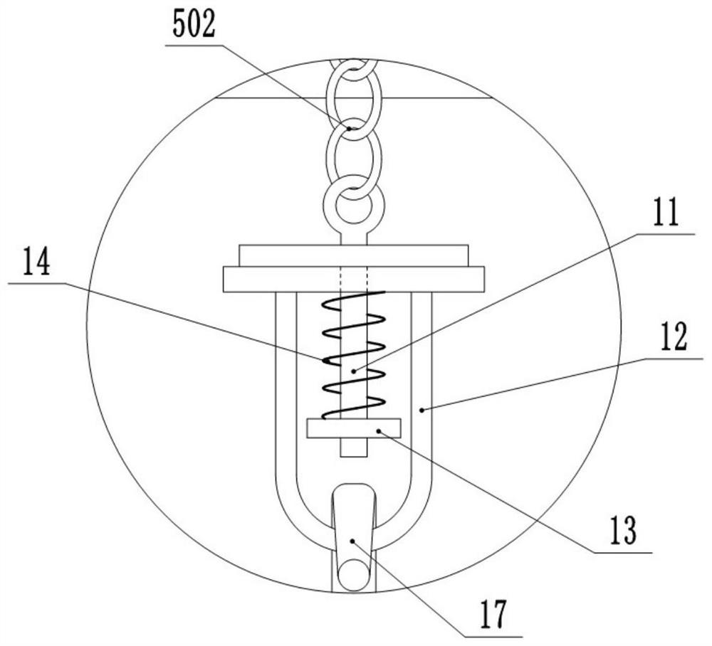
[0024] This embodiment is basically as figure 1 Shown: an anti-blocking raw material unloading system, including an anti-blocking mechanism suspended and installed under the material tank 1, the anti-blocking mechanism includes a vibration motor 2, a horizontal box 3, a mounting frame 4 and several cable chains 5, this embodiment Among them, the number of cable chains 5 is four, and the four cable chains 5 are located at the front side and the rear side of the installation frame 4 in pairs. The vibration motor 2 and the horizontal box body 3 are all fixedly installed on the mounting frame 4 by bolts, the vibration motor 2 is used to drive the horizontal box body 3 to vibrate, and the vibration motor 2 and the horizontal box body 3 are connected by bolts.
[0025] The top wall of the horizontal box 3 is provided with a material inlet, the side wall of the horizontal box 3 is provided with a discharge port, and the bottom of the tank 1 is provided with a discharge port, and the ...
Embodiment 2
[0036] The difference between this embodiment and Embodiment 1 is that: Figure 4 As shown, an isolation box 19 is welded in the horizontal box 3, and a rotating shaft 20 is connected to the isolation box 19 through bearing rotation. , In this embodiment, the number of stirring blades 21 is two, and the stirring blades 21 are located outside the isolation box 19 . Moreover, a sealing ring is provided between the rotating shaft 20 and the top wall of the isolation box 19 to prevent raw materials from entering the isolation box 19 . The bottom end of rotating shaft 20 stretches out the bottom wall of horizontal box body 3 and mounting frame 4, and the bottom surface of mounting frame 4 is fixedly installed with the driving motor 22 that is used to drive rotating shaft 20 to rotate by bolt, and the output end of driving motor 22 is connected with speed reducer 23. The bottom end of the rotating shaft 20 is connected.
[0037] In this embodiment, start the driving motor 22, and ...
PUM
 Abstract
Description
Claims
Application Information
 - R&D
- Intellectual Property
- Life Sciences
- Materials
- Tech Scout
- Unparalleled Data Quality
- Higher Quality Content
- 60% Fewer Hallucinations
Browse by: Latest US Patents, China's latest patents, Technical Efficacy Thesaurus, Application Domain, Technology Topic, Popular Technical Reports.
© 2025 PatSnap. All rights reserved.Legal|Privacy policy|Modern Slavery Act Transparency Statement|Sitemap|About US| Contact US: help@patsnap.com


