A refrigerator door
A refrigerator door and door frame technology, which is applied to cooling fluid circulation devices, household refrigeration devices, lighting and heating equipment, etc., can solve the problems of high production cost and high cost of refrigerator doors, and improve production efficiency and production quality. The effect of cost reduction, simple and quick assembly
- Summary
- Abstract
- Description
- Claims
- Application Information
AI Technical Summary
Problems solved by technology
Method used
Image
Examples
Embodiment 1
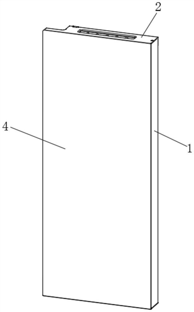
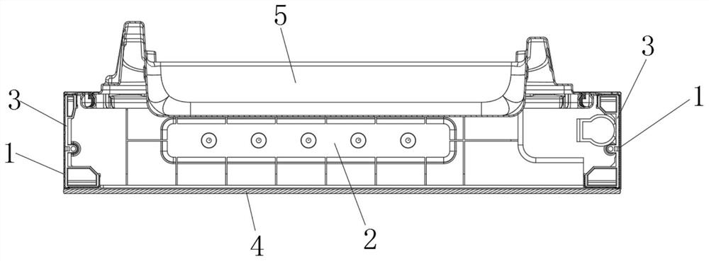
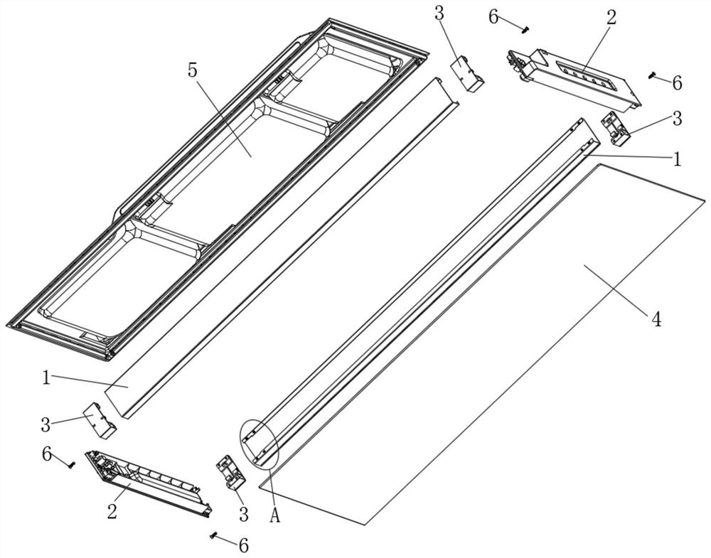
[0057] like Figure 1-3 As shown, a refrigerator door body includes a door frame, a glass plate 4, and a door lining 5;
[0058] The door frame includes end blocks 1 located on the left and right sides and trim strips 2 located on the upper and lower sides enclosing a rectangular structure; the end blocks 1 are sheet metal parts, that is, the end blocks 1 in this application are made of sheet metal materials, and the The material cost of gold is lower than that of plastic materials such as aluminum alloy, injection molding and extrusion. Figure 4 As shown, the end stop 1 includes an end plate 11, the front and rear sides of the end plate 11 are vertically turned to the inside of the door frame to form a side plate 12, and the ends of the two side plates 12 are vertically turned toward each other to form an end stop flange 13. ; The end plate 11, the side plate 12, and the end stop flange 13 enclose the end stop card slot 14;
[0059] The upper and lower ends of the end stop s...
Embodiment 2
[0066] On the basis of Example 1, as Figure 7 As shown, the end stop inserts 3 are arranged in an up-down symmetrical structure; the end stop inserts 3 are in an up-down symmetrical structure, so the same end stop insert 3 can be used on both the upper end of the end stop 1 and the end stop The lower end of 1 increases the versatility of end stop insert 3;
[0067] Positioning steps 15 are provided at the upper and lower ends of the end block flanging 13;
[0068] The side of the end block insert 3 facing the upper end block flange 13 of the corresponding end block 1 is provided with a positioning protrusion 31 which is matched with the corresponding positioning step 15.
[0069] Preferably, the upper and lower ends of the end stop flange 13 are respectively provided with two end stop punching holes 16;
[0070] The side of the end stop insert 3 facing the upper end stop flange 13 of the corresponding end stop 1 is provided with insert connection holes 32 corresponding to t...
Embodiment 3
[0075] On the basis of Example 2, as Figure 5-6 As shown, two decorative strip card bodies 21 are respectively provided on both ends of the side surface of the decorative strip 2 facing the end stop 1;
[0076] The end block insert 3 is provided with an insert slot 33 that is adapted to the trim strip card body 21 on the corresponding trim strip 2; specifically, the insert slot 33 is arranged symmetrically up and down;
[0077] The positioning protrusion 31 is arranged on the insert slot 33 .
[0078] Preferably, a decorative strip hook 22 is provided at an outer end of one side of the decorative strip card body 21;
[0079] One side of the insert slot 33 is provided with two up and down symmetrical insert slots 34 which are respectively matched with the trim hooks 22 on the corresponding trim 2.
[0080] Preferably, both ends of the decorative strip 2 are provided with a decorative strip threaded hole 23 extending axially along the vertical direction; the decorative strip ...
PUM
 Abstract
Description
Claims
Application Information
 - R&D
- Intellectual Property
- Life Sciences
- Materials
- Tech Scout
- Unparalleled Data Quality
- Higher Quality Content
- 60% Fewer Hallucinations
Browse by: Latest US Patents, China's latest patents, Technical Efficacy Thesaurus, Application Domain, Technology Topic, Popular Technical Reports.
© 2025 PatSnap. All rights reserved.Legal|Privacy policy|Modern Slavery Act Transparency Statement|Sitemap|About US| Contact US: help@patsnap.com


