
Ovality detection device and detection method

A detection device and ellipticity technology, which is applied in the field of mechanical processing, can solve problems such as affecting the light transmission effect, inaccurate detection results, and inability to work, and achieve the effects of controllable and adjustable accuracy, convenient operation, and improved accuracy

Active Publication Date: 2021-03-02
SICC CO LTD
View PDF13 Cites 3 Cited by
  • Summary
  • Abstract
  • Description
  • Claims
  • Application Information

AI Technical Summary

Problems solved by technology

Existing ellipticity detection devices are mainly based on optical detection, and generally have high requirements for the cleanliness of the detection environment. When using this detection device in a factory with a lot of dust, it is easy to affect the light transmission effect due to dust accumulation and coverage, resulting in inaccurate detection results. Accurate or Won't Work Issues

Method used


Image

  • Ovality detection device and detection method
  • Ovality detection device and detection method
  • Ovality detection device and detection method

Examples


Embodiment 1

[0048]Embodiment 1. An ellipticity detection device

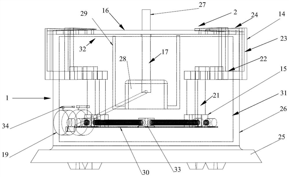
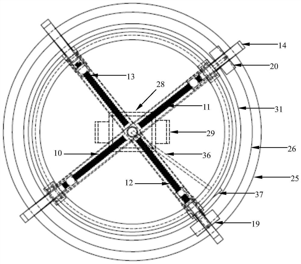
[0049]Such asfigure 1 withfigure 2 As shown, this embodiment provides an ellipticity detection device, including: a frame 1, a rotating platform 16, a probe assembly, and a control assembly,

[0050]The frame 1 includes a base 25 and a cylindrical shell fixed above the base 25. The shell includes two layers, an outer shell 26 and an inner shell 31. The top of the outer shell 26 has no bottom, and the top of the inner shell 31 is provided with Upper bottom 32,

[0051]The rotating platform 16 is set above the frame 1 and can rotate in both directions, such asfigure 1 Shown is located directly above the upper base 32, close to each other in parallel but not in contact with the upper base 32. The rotating platform 16 is circular and horizontally arranged for placing the object to be tested. The lower center of the rotating platform 16 is connected to the upper end of the rotating shaft 17. It rotates smoothly with the axial rotation of the s...

Embodiment 2

[0069]Embodiment 2. A method for detecting ellipticity

[0070]Use the ellipticity detection device of embodiment 1, and the method includes:

[0071]S1. Use a fixed component (ie, probe assembly) to fix the object to be measured in a plane a (such as the surface where the upper surface of the rotating platform 16 is located), and the fixed position is located at the four points on the outer or inner edge of the object to be measured , The four points are located on a circle b of the plane a where the outer or inner edge of the object to be measured is located;

[0072]S2, at a fixed position, move the fixed part away from the outer edge or inner edge of the object to be measured by a certain distance c along the radial direction of the inner circle b of the plane a;

[0073]S3. Make the object to be measured make two mutually opposite axial rotations in plane a, and if the fixed part jams the outer or inner edge of the object to be measured during each axial rotation, record each time it is st...


PUM


Abstract

The invention discloses an ovality detection device and an ovality detection method. The device comprises a machine frame, a rotating platform arranged on the machine frame, a driving device, a probeassembly and a control assembly, the upper surface of the rotating platform is used for containing an object to be measured, the probe assembly comprises at least one probe, and each probe can reciprocate in at least one plane a in the radial direction of a circle b; each probe can be in contact with the outer edge or the inner edge of an object to be measured, the object to be measured is fixed through sliding friction force at the contact position, and the control assembly is connected with each probe and can control each probe to do reciprocating motion. According to the method, the maximumdiameter point of a to-be-detected object is clamped through a probe assembly, whether the same point is clamped by forward and reverse rotation or not is observed in a forward and reverse rotation mode, and the ovality of the to-be-detected object is checked. The device and method have the advantages of being reasonable in design, simple, practical, convenient to operate, controllable and adjustable in precision and small in environmental interference.

Description

Technical field[0001]The invention relates to the technical field of mechanical processing, in particular to an ellipticity detection device and a detection method.Background technique[0002]Ovality is also called out-of-roundness, which refers to the difference between the largest diameter and the smallest diameter on the cross-section of products with circular cross-sections, such as gears, round steel, and round steel pipes, which is the value of ovality. Most of the existing ellipticity detection devices are mainly based on optical detection, and generally require high cleanliness of the detection environment. Using this detection device in a dusty factory is likely to affect the light transmission effect due to dust accumulation and coverage, resulting in poor detection results. Questions of accuracy or inability to work.Summary of the invention[0003]In view of the defects in the prior art, the purpose of the present invention is to provide an ellipticity detection device and a ...

Claims


Application Information

Patent Timeline
Patent Type & Authority Applications(China)
IPC IPC(8): G01B21/20
CPCG01B21/20
Inventor 蒋文广李印
Owner SICC CO LTD
Learn More