

Deployable Mechanism of Modular Parabolic Thin Film Antenna Driven by Hyperelastic M-shaped Rod
A parabolic cylinder and unfolding mechanism technology, which is applied to antennas, folded antennas, and retractable units, etc., can solve the problems of lower reliability of mass unfolding, affecting the folded volume, the folded volume and the increase of the overall mechanism mass, etc., so as to reduce the total mechanism. Quality, lower launch cost, simple and reliable effect of mechanism deployment
- Summary
- Abstract
- Description
- Claims
- Application Information
AI Technical Summary
Problems solved by technology
Method used
Image

Examples
Embodiment 1
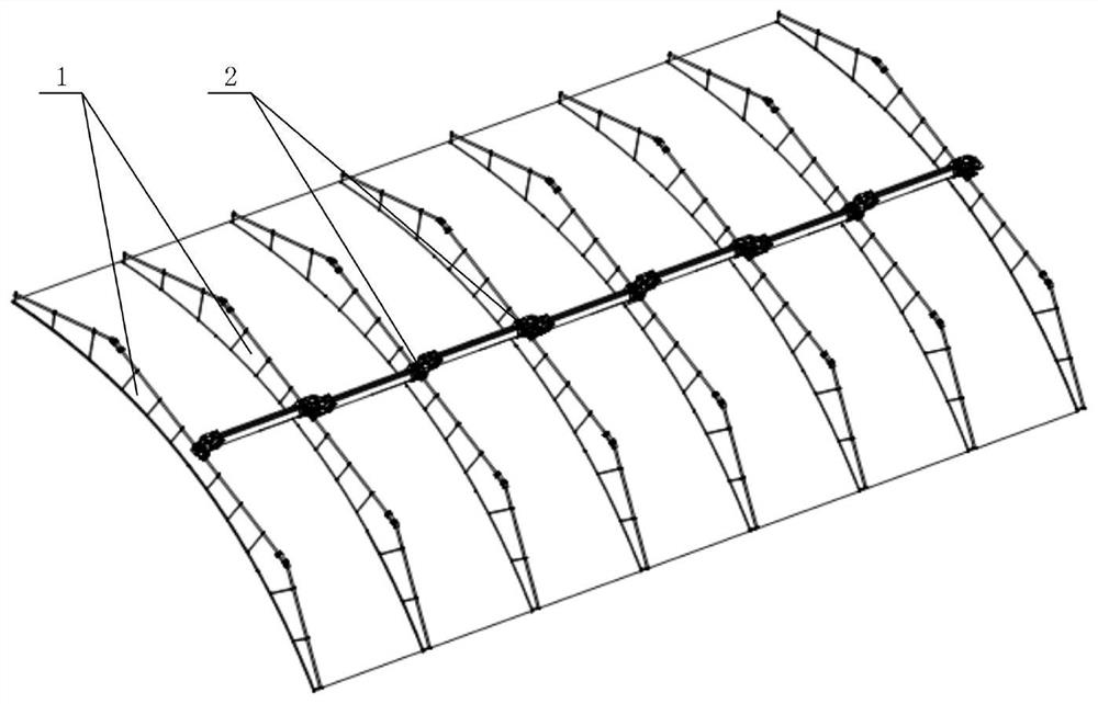
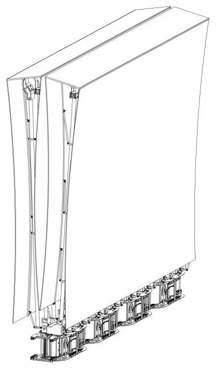
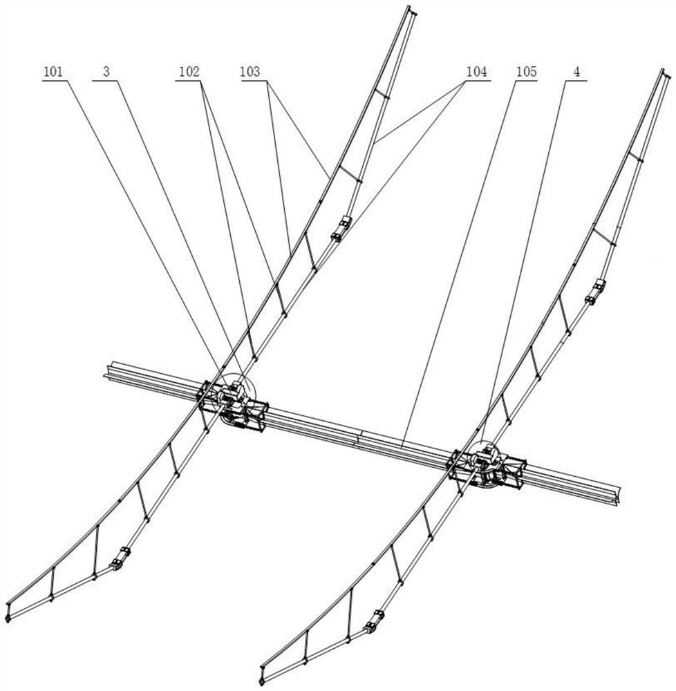
[0032] Such as Figure 1-Figure 4 as shown, figure 1It is the structure diagram of the unfolded state of the expandable mechanism of the modularized parabolic cylindrical film antenna driven by the hyperelastic M-shaped rod; figure 2 It is the structural diagram of the folded state of the expandable mechanism of the modular parabolic cylindrical film antenna driven by the hyperelastic M-shaped rod; image 3 It is the connection structure diagram of the expandable mechanism of the modularized parabolic cylindrical film antenna driven by the hyperelastic M-shaped rod; Figure 4 is a cross-sectional view of the M-shaped bar.
[0033] The expandable mechanism of the modularized parabolic cylindrical film antenna driven by the hyperelastic M-shaped rod of the present invention includes a plurality of transverse folding modules 1, a plurality of M-shaped rod extension modules 2, a plurality of drum forward rotation transmission modules 3 and a drum Reverse transmission module 4 ...
Embodiment 2
[0041] Such as Figure 5 as shown, Figure 5 It is a structural view of the superelastic hinge structure; the superelastic hinge includes a second joint 703 , a third bolt 704 , a fixing plate 705 , a superelastic reed 706 , and a first joint 708 .
[0042] The superelastic reed 706 is fixedly installed on the first joint 708 and the second joint 703 by the fixed pressure plate 705 through the third bolt 704, and the first joint 708 and the second joint 703 are respectively arranged at the ends of two adjacent carbon fiber rods 104 .
[0043] The spring sheet of the installation structure has good elastic properties, high strength, and good mechanical properties to meet the design requirements and actual needs.
[0044] The fourth pin 701 is used to connect the drag cable 102 to the parabolic skeleton 103, and the fifth pin 702 is used to connect adjacent parabolic skeletons 103. A drag ring 710 is provided on the carbon fiber rod 104. , the cable ring 710 is sleeved on the...
Embodiment 3
[0046] Such as Figure 6 as shown, Figure 6 It is a structural view of the M-shaped rod extension module; the M-shaped rod flattened expansion part includes an M-shaped expansion plate 201, a second compression spring 212, a fifth bolt 213, a support column 214, a fourth bolt 215, and a sleeve The rolling rod 216 , the floor support column 220 , the upper floor 221 and the lower floor 211 .
[0047] The support column 214 is fixedly installed with the base plate support column 220 through the fourth bolt 215 as the base plate frame support structure of the upper base plate 221 and the lower base plate 211, and the sleeve rolling rod 216 is installed on the base plate. On the support column 214, the second compression spring 212 can telescopically move on the bottom plate, one end is fixed on the bottom plate, the other end is fixed on the telescopic structure part, and the end of the telescopic structure part is fixed by the fifth bolt 213 The M-shaped expansion plate 201 i...
PUM
 Abstract
Description
Claims
Application Information