System for monitoring bearings

A technology for monitoring systems and bearings, applied in the direction of bearings, ball bearings, roller bearings, etc., can solve the problems of complex, expensive technology, and the inability to add sensor systems, etc., to achieve the effect of preventing damage and moisture, and avoiding weakening

Pending Publication Date: 2021-03-02
尼克奥地利有限公司 +1
View PDF18 Cites 2 Cited by
  • Summary
  • Abstract
  • Description
  • Claims
  • Application Information

AI Technical Summary

Problems solved by technology

[0014] With all these modules it is not possible to add sensor systems to existi

Method used


Image

  • System for monitoring bearings
  • System for monitoring bearings
  • System for monitoring bearings

Examples


Embodiment Construction

[0041] In the drawings, the same or similar parts are marked with the same reference numerals. Unless otherwise stated, directions refer to the axial and radial directions of the bearings shown, or to the directions in the plane of the drawing. To the extent technically feasible and possible, individual features of different designs may be added to or interchanged with features of other designs. These variations are hereby expressly included in the present invention, even if they are not described in detail again.

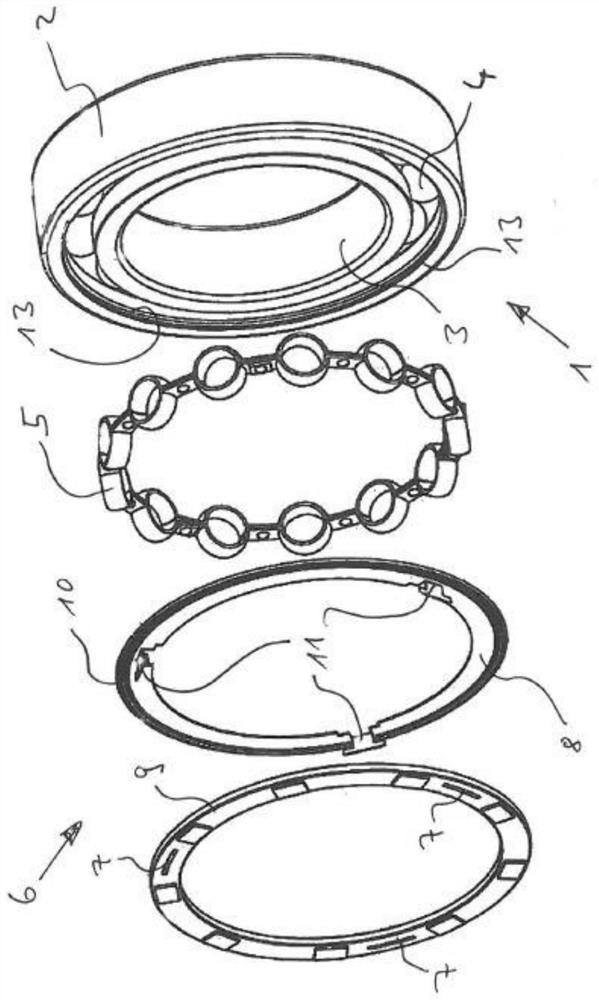
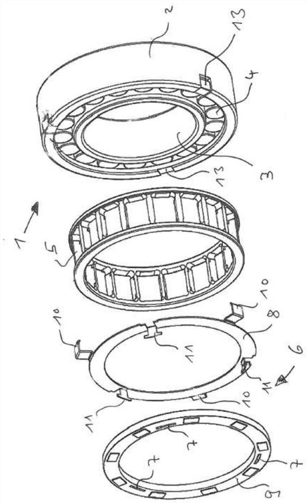
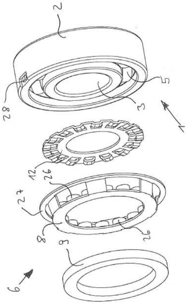
[0042] figure 1 A schematic exploded view of a first type of bearing 1 with a bearing monitoring system 6 according to the invention is shown, wherein the bearing housing and the shaft are not shown. The bearing 1 is composed of a first race 2 and a second race 3. In this design, the first race 2 is the outer race of the bearing and the second race 3 is the inner race of the bearing 1. The roller elements 4 are arranged between the first race 2 and the second ra...


PUM


Abstract

The invention relates to a system for monitoring bearings, preferably for roller bearings having a first bearing ring and a second bearing ring mounted such as to rotate relative to one another, saidsystem comprising at least one sensor element including one or more sensors for the contactless detection of the state of the bearings, at least one transmitter for transmitting a signal, and a powerunit for supplying power to the sensor element and the transmitter, in which a sensor element is connected to the transmitter and mounted in a supporting element that is fitted to the bearing using anadapter. The resulting bearing-monitoring system is a system which can be installed in a simple and cost-effective manner and which can be retrofitted to almost any type of bearing.

Description

technical field [0001] The invention relates to a bearing monitoring system, preferably for a roller bearing having a first bearing ring and a second bearing ring, which are rotatably arranged relative to each other, said The bearing monitoring system has at least one sensor element, at least one transmitter for transmitting signals, and a power supply unit for supplying the sensor element and the transmitter with electrical energy. Background technique [0002] Bearing monitoring systems are known from the prior art. [0003] For example, European patent EP1292831B1 shows an improved bearing with two rows of roller elements, where the sensor is located between the first and second row of roller elements. The sensor unit is carried by the inner ring and consists of sensor, microprocessor, transmitter and power supply. The design described here is disadvantageous because additional space is required between the rows for the sensors. [0004] Furthermore, in US2005 / 0141795A...

Claims


Application Information

Patent Timeline
IPC IPC(8): F16C19/52F16C41/00
CPCG01P3/443F16C19/06F16C19/26F16C19/522F16C19/525F16C19/527F16C33/427F16C33/4635F16C33/585F16C33/586F16C41/00F16C41/004F16C41/008F16C2226/74
Inventor 克劳斯·格里森伯格托马斯·威茨勒圭多·费兹迈尔大卫·海德马提亚·霍尔泽巩特尔·魏德霍兹凯文·卡斯帕塞尔吉奥·桑托·多明戈
Owner 尼克奥地利有限公司
Why Eureka
Try Eureka