Metal cutting tool convenient to disassemble and assemble

A technology for metal cutting and easy disassembly and assembly. It is applied in the direction of metal processing equipment, metal processing machinery parts, milling cutters, etc. It can solve the problems of cumbersome disassembly and assembly, and achieve the effects of short disassembly and assembly time, simple structure and reasonable design.

Inactive Publication Date: 2021-03-05
江苏海博工具产业研究院有限公司
View PDF0 Cites 1 Cited by
  • Summary
  • Abstract
  • Description
  • Claims
  • Application Information

AI Technical Summary

Problems solved by technology

[0004] The purpose of the present invention is to solve the disadvantages of cumbersome disassembly and assembly in the prior art, and propose a metal cutting tool that is convenient to disassemble

Method used


Image

  • Metal cutting tool convenient to disassemble and assemble
  • Metal cutting tool convenient to disassemble and assemble

Examples


Embodiment 1

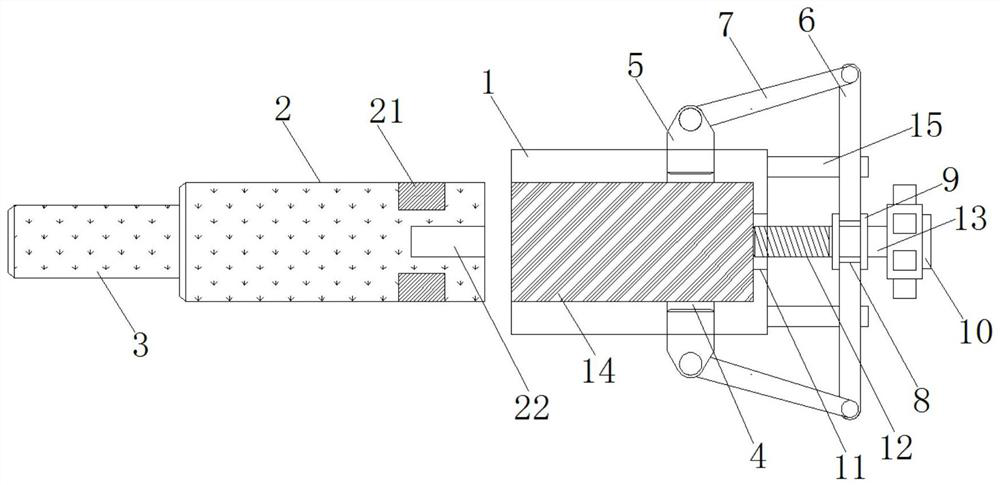
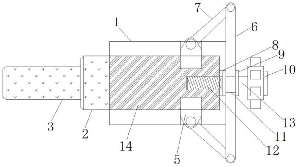
[0017] Embodiment 1, during installation, the knife handle 2 is inserted into the installation groove 14, and the locking groove 21 is located on one side of the slider 5. After the handle 10 is rotated, the rotating rod 13 and the screw rod 12 rotate simultaneously, and the screw rod 12 is screwed into the screw hole 22, the rotating rod 13 rotates in the through hole 8. Since the screw rod 12 is displaced when it rotates, the rotating rod 13 rigidly connected with it also moves at the same time, and the baffle plate 9 pushes the push plate 6 when moving with the rotating rod 13. Slide on the guide rod 15, the connecting rod 7 on both sides is forced to rotate, and the other end pushes the slider 5 to slide in the middle. When the screw rod 12 is fully tightened, the slider 5 just slides to the inside of the locking groove 21, and the knife The handle 2 is clamped tightly, and at this time the push plate 6 is tightly attached to the end of the mounting seat 1, as figure 2 As...

Embodiment 2

[0018] Embodiment 2, when dismounting, the personnel rotates the handle 10 in the opposite direction, the screw rod 12 gradually selects the inside of the screw hole 22, the baffle plate 9 on the other side pulls the push plate 6 to reset, and the limit block acts to limit the stroke of the push plate 6 Purpose, when the push plate 6 is in contact with the limit block, the slider 5 is pulled out from the inside of the locking groove 21, and the handle 2 can be removed.


PUM


Abstract

The invention relates to the technical field of metal cutting tools, in particular to a metal cutting tool convenient to disassemble and assemble. The metal cutting tool solves the defect of complicated disassembly and assembly in the prior art, and comprises a mounting seat and a tool handle, a mounting groove is formed in the mounting seat, and side grooves which are symmetrically formed in theside wall of the mounting groove; and a sliding block is slidably connected into each side groove, a connecting rod is movably hinged to one side of each sliding block, a push plate is movably hingedto the other ends of the connecting rods, guide rods are welded to one end of the mounting base, the push plate is slidably arranged outside the guide rods, and a rotating rod is rotatably mounted inthe center of the push plate. The metal cutting tool is simple in structure and reasonable in design; and through the arrangement of the connecting rods, the sliding blocks, a handle, a screw rod, a screw hole and other structures, only one screw rod is adopted for fixed installation, the disassembly and assembly purposes can be achieved along with screwing and unscrewing of the screw rod, the disassembly and assembly time is short, the fixity is high, a large amount of manpower and working hours are saved, and personnel use is more convenient.

Description

technical field [0001] The invention relates to the technical field of metal cutting tools, in particular to a metal cutting tool that is easy to assemble and disassemble. Background technique [0002] The structure of various tools is composed of a clamping part and a working part. The clamping part and the working part of the overall structure tool are made on the cutter body; the working part (cutter teeth or blade) of the insert structure tool is mounted on the cutter body, and the clamping part of the tool has two holes and a handle. kind. The tool with a hole is set on the main shaft or mandrel of the machine tool by means of the inner hole, and the torsional moment is transmitted by means of an axial key or an end face key, such as a cylindrical milling cutter, a shell face milling cutter, etc. [0003] At present, multiple screws, bolts and nuts are used in the installation of knives, and the assembly mechanism is complicated. It takes a lot of time and manpower to...

Claims


Application Information

Patent Timeline
Patent Type & Authority Applications(China)
IPC IPC(8): B23Q3/12B23Q3/14B23C5/26
CPCB23C5/26B23Q3/12B23Q3/14
Inventor 陈明马海善
Owner 江苏海博工具产业研究院有限公司
Why Eureka
Try Eureka