Al technical title is built by PatSnap Al team. It summarizes the technical point description of the patent document.
A technology of mixing equipment and construction cement, which is applied in the direction of mixing operation control, cement mixing device, mixing operation control device, etc.
Inactive Publication Date: 2021-03-05
谭桂珍
View PDF0 Cites 1 Cited by
Summary
Abstract
Description
Claims
Application Information
AI Technical Summary
This helps you quickly interpret patents by identifying the three key elements:
Problems solved by technology
Method used
Benefits of technology
Problems solved by technology
[0002] Cement mixing equipment is a common construction machinery, but general construction cement mixing equipment only has the function of mixing and has no function of screening impurities.
Method used
Image
Click on the blue label to locate the original text in one second.
Reading with bidirectional positioning of images and text.
Examples
specific Embodiment approach 1
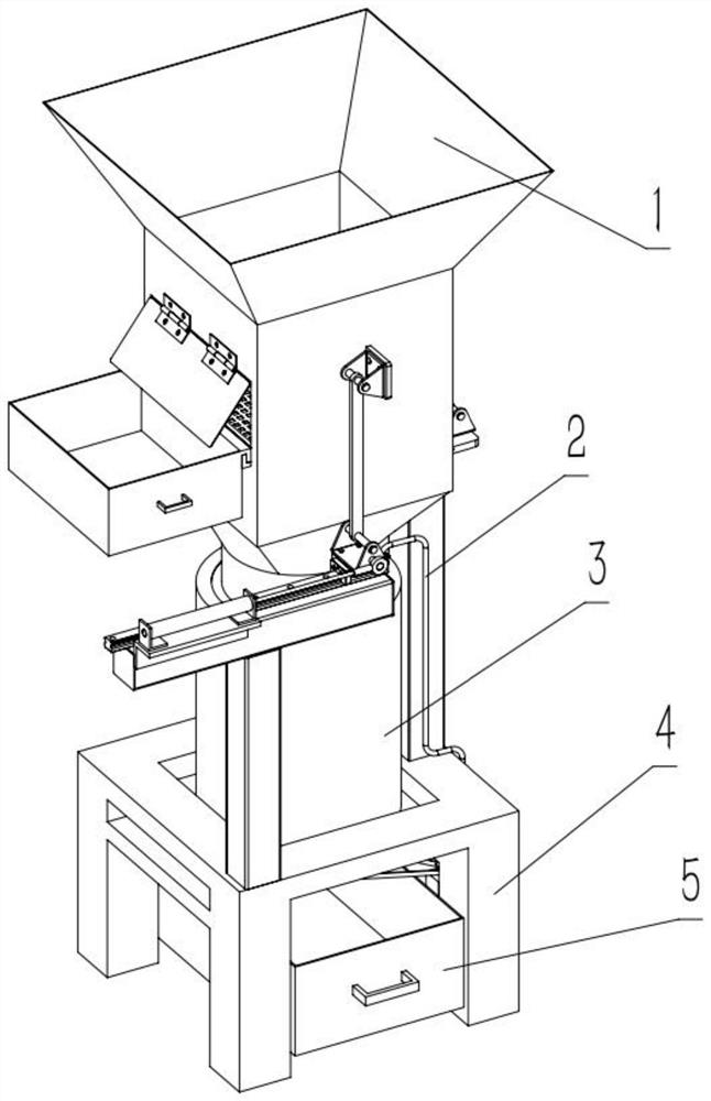
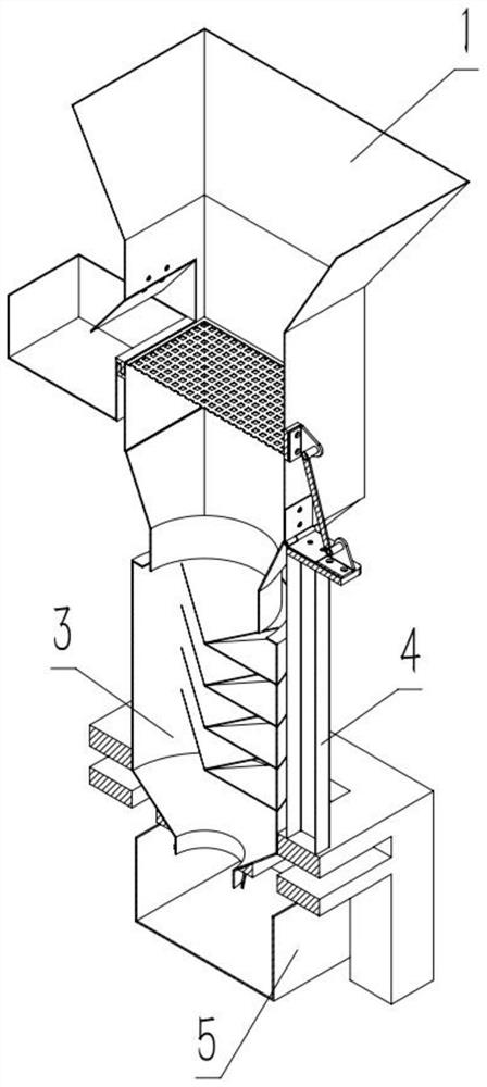
[0029] Combine below Figure 1-11 Describe this embodiment, a construction cement mixing equipment, including a screening device 1, a water pipe 2, a stirring device 3, a base 4, and a skip 5, the screening device 1 and the base 4 are tightly connected, and the water pipe 2 and the base 4 is fixedly connected, the stirring device 3 is connected with the base 4, and the skip 5 is connected with the base 4.
specific Embodiment approach 2
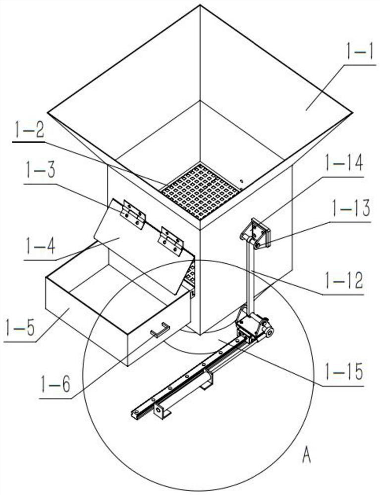
[0031] Combine below Figure 1-11Describe this embodiment, this embodiment will further explain Embodiment 1. The screening device 1 includes a mud injection port 1-1, a screen 1-2, a hinge A 1-3, and a baffle plate 1. -4, scrap frame one 1-5, handle one 1-6, slide rail one 1-7, cylinder mounting seat one 1-8, cylinder one 1-9, connecting rod fixing seat A one 1-10, connecting rod Fixed shaft A-1-11, connecting rod-1-12, connecting rod fixed shaft B-1-13, connecting rod fixing seat B-1-14, blanking port-1-15, hinge B-1-16 , tension spring one 1-17, connecting rod fixing seat C-1-18, connecting rod fixing shaft C-1-19, the four sides of screen one 1-2 are welded and connected with the inner wall of mud injection port one 1-1, hinge A The rear end of A 1-3 is fixedly connected with the upper end of the left opening of the mud injection port 1-1, the front end of the baffle plate 1-4 is fixedly connected with the rear end of the hinge A 1-3, and the rear end of the waste frame 1...
specific Embodiment approach 3
[0034] Combine below Figure 1-11 Describe this embodiment. This embodiment will further explain Embodiment 1. When the extension spring 1-17 is in the retracted state of the cylinder 1-9, the extension spring 1-17 is in a stretched state. -9 pushes out under the state, extension spring one 1-17 is contraction state.
PUM
Abstract
The invention relates to the field of buildings, in particular to building cement mixing equipment. Large-particle cement and impurities can be screened out, and the quality of the screened cement after being mixed and stirred is improved. The equipment comprises a screening device, a water pipe, a stirring device, a base, and a skip car. Air cylinders the screening device retract to drive a sliding rail to move, the sliding rail moves to enable a connecting rod fixing base A to move, meanwhile a connecting rod fixing shaft A is driven to move, through the pulling effect of the connecting rodfixing shaft A on a connecting rod, the connecting rod moves and inclines, the connecting rod drives a connecting rod fixing shaft B to move, meanwhile a connecting rod fixing base B is driven to move, through movement of the connecting rod fixing base B, a mud injection opening is pulled to incline, so that a material baffle is opened, the large cement particles and impurities on a screen slide into a waste material frame along the screen, and the effects that the screening device screens the large cement particles and the impurities, and the quality of the stirred cement is improved are achieved.
Description
technical field [0001] The invention relates to the construction field, in particular to a cement mixing equipment. Background technique [0002] Cement mixing equipment is a common construction machinery, but general construction cement mixing equipment only has the function of mixing and has no function of screening impurities. Contents of the invention [0003] The purpose of the present invention is to provide a construction cement mixing equipment, which can screen out large particles of cement and impurities, and improve the quality of the screened cement after mixing. [0004] The purpose of the present invention is achieved through the following technical solutions: [0005] A construction cement mixing equipment, comprising a screening device, a water pipe, a stirring device, a base, and a feeding truck, the screening device is tightly connected to the base, the water pipe is fixedly connected to the base, the stirring device is connected to the base, and the fee...
Claims
Application Information
Patent Timeline
Application Date:The date an application was filed.
Publication Date:The date a patent or application was officially published.
First Publication Date:The earliest publication date of a patent with the same application number.
Issue Date:Publication date of the patent grant document.
PCT Entry Date:The Entry date of PCT National Phase.
Estimated Expiry Date:The statutory expiry date of a patent right according to the Patent Law, and it is the longest term of protection that the patent right can achieve without the termination of the patent right due to other reasons(Term extension factor has been taken into account ).
Invalid Date:Actual expiry date is based on effective date or publication date of legal transaction data of invalid patent.
