Method and system for categorizing powertrain torque requests

A technology of power transmission system and vehicle system, applied in the field of power transmission system, can solve problems such as temperature rise of power transmission system components, and achieve the effect of high power transmission system performance

Pending Publication Date: 2021-03-05
FORD GLOBAL TECH LLC
View PDF0 Cites 1 Cited by
  • Summary
  • Abstract
  • Description
  • Claims
  • Application Information

AI Technical Summary

Problems solved by technology

For example, if the vehicle is operated in very warm ambient conditio

Method used


Image

  • Method and system for categorizing powertrain torque requests
  • Method and system for categorizing powertrain torque requests
  • Method and system for categorizing powertrain torque requests

Examples


Embodiment Construction

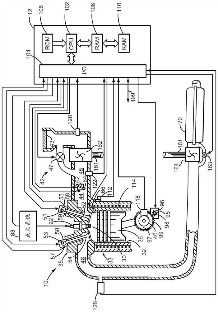
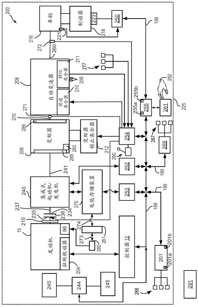
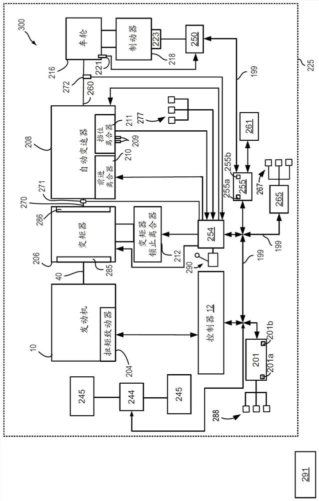
[0015] This specification is concerned with controlling drivetrain torque and achieving desired results for the drivetrain. The present description may be used to operate a vehicle that includes an autonomous driver (eg, an automated non-human driving device, such as an embedded controller, that provides commands to the vehicle to move the vehicle to a requested destination). figure 1 An engine that may be included in a powertrain is shown. like figure 2 and image 3 As shown, the engine may be included in different drivetrain configurations. However, the description is also applicable to other powertrain configurations not shown. For example, this specification applies to pure electric vehicles that only include electric motors as a propulsion source. Figure 4 A control system block diagram is shown in to demonstrate exemplary powertrain components and signal flow. Figure 5 and Image 6 A method for operating a vehicle is shown in . at last, Figure 7 shown in Fi...


PUM


Abstract

The disclosure provides a method and system for categorizing powertrain torque requests. A method for operating a powertrain of an autonomous vehicle is described. In one example, the autonomous driver may supply a torque request and a torque or power urgency assessment to a powertrain controller. The powertrain controller may monitor vehicle control system parameters based on the driver demand torque and the torque or power urgency assessment.

Description

technical field [0001] The present description relates to methods and systems for operating a powertrain of a vehicle. A vehicle may include an autonomous driver who requests torque from the driveline so that the vehicle can reach its intended destination. Background technique [0002] When a human driver requests power from the driveline, the output of the driveline of the vehicle may be limited such that the likelihood of degradation of driveline components may be reduced. For example, if the vehicle is operating in very warm ambient conditions, the temperature of one or more drivetrain components may increase. The powertrain controller may perform mitigating actions to reduce the temperature of one or more powertrain components such that the likelihood of one or more component degradation may be reduced. Mitigation actions may include reducing powertrain output power and / or reducing powertrain efficiency to reduce powertrain component temperatures. Additionally, when c...

Claims


Application Information

Patent Timeline
IPC IPC(8): B60W30/192B60W50/00
CPCB60W30/192B60W50/00B60W2050/0043B60K6/48B60K2006/268B60K2006/4825B60W30/184B60W50/029B60W2050/0297B60W2710/105B60W2710/1061B60W60/00186B60W60/007B60W2556/45Y02T10/62B60W40/08B60W50/10B60W2040/0818B60W2510/105B60W20/13G05D1/021
Inventor 斯科特·斯泰德蒙·汤普森罗伯特·雷·詹特斯大卫·汉考克
Owner FORD GLOBAL TECH LLC
Why Eureka
Try Eureka