Multi-size liquid injection device for fluid packaging bags
A technology of liquid injection device and packaging bag, which is applied in the directions of packaging, transportation and packaging, and the type of packaged items. It can solve the problems of low work efficiency, increased cost, and high labor intensity, so as to avoid mixture precipitation, improve integration, and improve The effect of work efficiency
- Summary
- Abstract
- Description
- Claims
- Application Information
AI Technical Summary
Problems solved by technology
Method used
Image

Examples
Embodiment Construction
[0024] In order to make the technical means, creative features, goals and effects achieved by the present invention easy to understand, the present invention will be further described below in conjunction with specific embodiments.
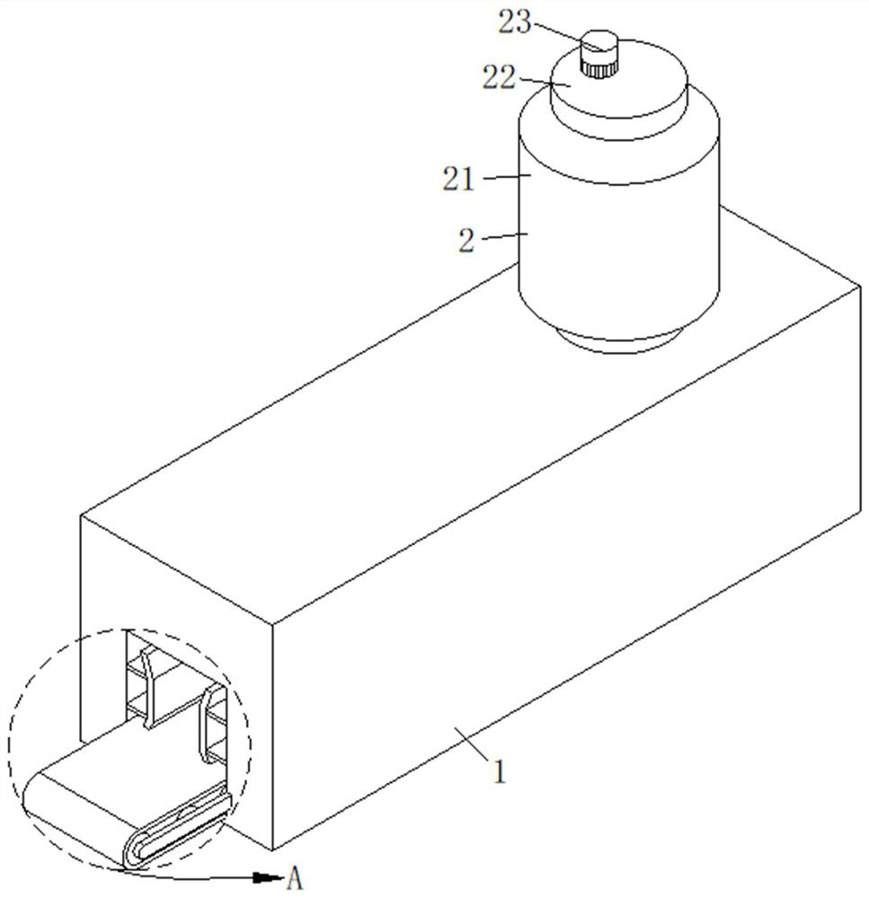
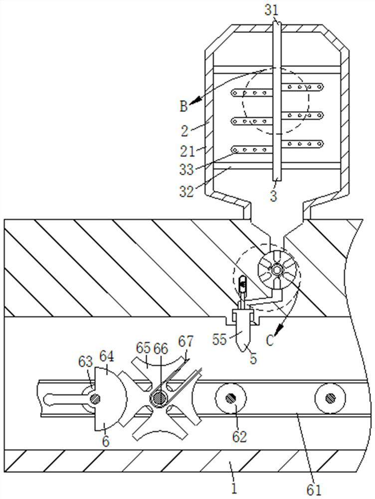
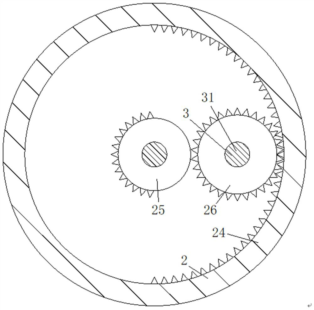
[0025] Such as Figure 1-Figure 7 As shown, a multi-size fluid packaging bag liquid injection device according to the present invention includes a main body 1, a reciprocating mechanism 2, a stirring mechanism 3, a quantitative mechanism 4, a liquid injection mechanism 5 and a delivery mechanism 6 for accelerating liquid mixing The uniform stirring mechanism 3 is arranged on the top of the main body 1, and the reciprocating mechanism 2 for causing the internal stirring parts of the stirring mechanism 3 to reciprocate is arranged on the top of the stirring mechanism 3 for quantitatively releasing and taking The quantitative mechanism 4 for liquid is arranged at the bottom end of the stirring mechanism 3, and the quantitative mechanism 4 is arranged...
PUM
 Abstract
Description
Claims
Application Information
 - Generate Ideas
- Intellectual Property
- Life Sciences
- Materials
- Tech Scout
- Unparalleled Data Quality
- Higher Quality Content
- 60% Fewer Hallucinations
Browse by: Latest US Patents, China's latest patents, Technical Efficacy Thesaurus, Application Domain, Technology Topic, Popular Technical Reports.
© 2025 PatSnap. All rights reserved.Legal|Privacy policy|Modern Slavery Act Transparency Statement|Sitemap|About US| Contact US: help@patsnap.com