[0043] Next, the technical solutions in the present application embodiment will be described in the present application embodiment, and it is clear that the described embodiments are merely the embodiments of the present application, not all of the embodiments. Based on the embodiments in the present application, all other embodiments obtained by those of ordinary skill in the art without making creative labor premises, all of the present application protected.
[0044] It is to be understood that the term "first", "second" is only used to describe the purpose to distinguish between the same type of technical features, and cannot understand or imply relative importance, order, and quantity of these technical features. The "first" technical feature can be referred to as "second" technical feature, "second" technical features can also be referred to as "first" technical features, and define "first", "second" Technical features may be expressly or implied to include one or more techniques. In addition, the meaning of "multiple" is two or more unless otherwise stated.
[0045] It is emphasized that in the description of the present application, the term "installation", "connected", "connection" should be made, unless otherwise specified and defined, and "Connect", "Connect",, for example, can be fixed, or detachable Connect, or integrate; it can be mechanical connection, or electrical connection; may be directly connected, or indirectly connected by an intermediate medium, which can be in the interior of the two elements. The specific meanings of the above terms in the present application can be understood in terms of one of ordinary skill in the art.
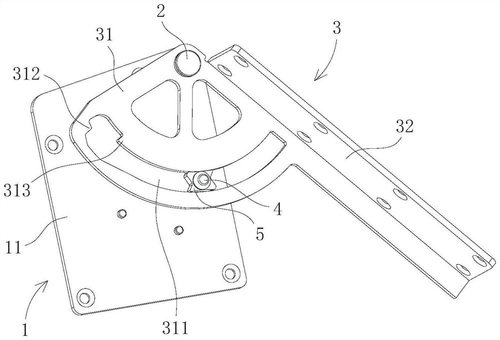
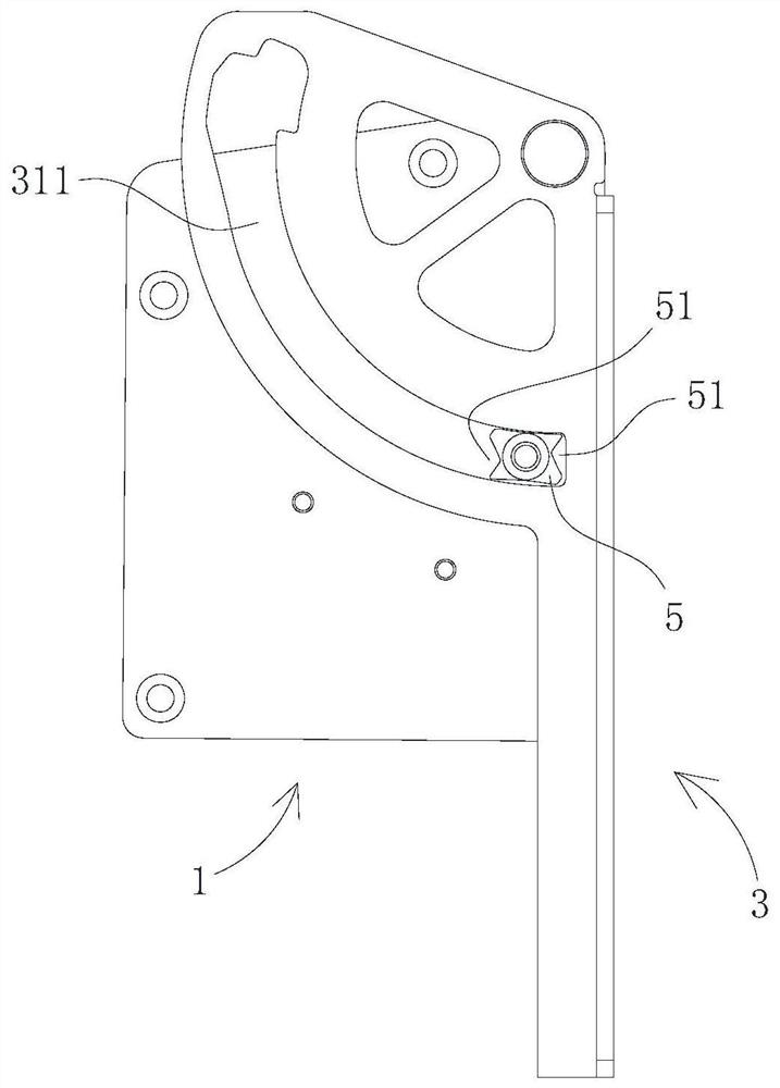
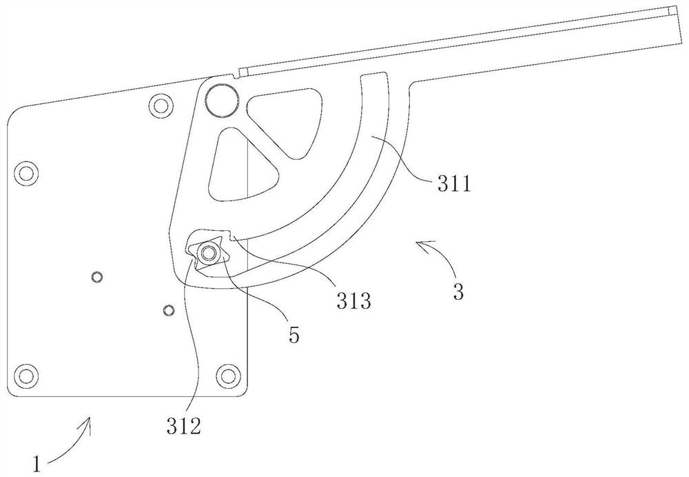
[0046] See figure 1 The embodiment of the present invention provides an articulated assembly including the first member 1, and rotates the second member 3 connected to the first member 1 and rotates through the second shaft member 4 and the first member 1. The locking member 5; the second member 3 is provided with an arcuate long strip 311 with a center of the axis of the first shaft member 2, and the edge of the curved long strip 311 is provided with a first convex portion 312 and a second convex. The portion 313, and the first convex portion 312 is provided at the first end of the curved long strip 311, and the second convex portion 313 is close to the first end of the curved long strip 311 and is relative to the first convex portion 312; The member 5 is provided in the curved long strip 311 and can move along the opposite rotation between the first member 1 and the second member 3, and both ends of the locking member 5 are provided. The groove 51 supplied by the first convex portion 312 and the second convex portion 313.
[0047]Further, the locking member 5 can be switched between the pre-lock state, the lock state, the unlocked state by rotation, where:
[0048] Such as image 3 As shown, the pre-lock state is within the recess 51 of the first convex portion 312 abutting one of the ends of the locking member 5, at this time, the locking member 5 is located first end, the first component of the curved long strip 311. 1 and the second component 3 can only occur relative rotation of the locking member 5 to the second end of the curved long strip 311;
[0049] Such as Figure 4 As shown, the lock state is within the groove 51 of the second convex portion 313 abutting one of the ends of the locking member 5, and the other end of the locking member 5 abuts against the edge of the curved long strip 311, at this time The relative rotation of the first member 1 and the second member 3 cannot cause the locking member 5 to the second end of the arcuate long strip hole 311, can only occur in the first part of the locking member 5 to the curved long strip 311 The relative rotation of one end movement;
[0050] Such as figure 2 , Figure 5 as well as Figure 6 As shown, the unlocked state is a state other than the pre-lock state and the lock state. At this time, when the locking member 5 is located between the two ends of the curved long strip 311, the first member 1 and the second member 3 can be The relative rotation of the two directions occurs, and if the locking member 5 is located at the first end of the curved long strip 311, the first member 1 and the second member 3 can only cause the locking member 5 to the curved long strip 311. The relative rotation of the second end movement, if the locking member 5 is located at the second end of the curved long strip 311, the first member 1 and the second member 3 can only cause the locking member 5 to the curved long strip hole. The relative rotation of the first end of 311.
[0051] Further, such as Figures 2 to 6 As shown, the opposing rotation of the first member 1 and the second member 3 can drive the locking member 5 to move smoothly between pre-locking state, lock state, unlocked state, and the specific work process is as follows:
[0052] Such as figure 2 As shown, the locking member 5 is located at the second end of the curved long strip 311, at this time, the locking member 5 is in a unlocked state;
[0053] Such as image 3 As shown, the first member 1 and the second member 3 cause relative to the first end of the locking member 5 to the arcuate long strip 311, when the locking member 5 reaches the first of the curved long strip 311 At the end, the first convex portion 312 pushes the lockout 5 to rotate the first rotation (in image 3 As an example, the direction of rotation is in the counterclockwise direction) and the bottom step into the groove 51 towards its groove 51, at this time, the locking member 5 becomes a pre-lock state;
[0054] Such as Figure 4 As shown, the first member 1 and the second member 3 are relatively rotated to the second end of the locking member 5 to the arcuate long strip 311 until the second convex portion 313 enters the recessed of the locking member 5 towards it. The slot 51 is in the bottom of the lock 51 to push the locking member 5 in the second rotation (in Figure 4 For example, the direction of rotation is counterclockwise) such that the locking member 5 abuts the edge of the curved long strip 311 away from one end of the second convex portion 313, at this time, the locking member 5 becomes the lock. At the stop, the first member 1 and the second member 3 cannot occur relative to the second end of the locking member 5 to the second end of the curved long strip 311;
[0055] Such as Figure 5 As shown, the relative rotation of the first member 1 and the second member 3 cause the locking member 5 to the first end of the curved long strip 311, when the locking member 5 reaches the arc-shaped long strip 311 At one end, the first convex portion 312 pushes the lockout 5 to rotate the third rotation (in Figure 5 For example, the direction of rotation is counterclockwise), at this time, the locking member 5 becomes the unlocked state by the lock state, and the first member 1 and the second member 3 can cause the locking member 5 to the curved long strip 311. The relative rotation of the second end movement;
[0056] Such as Figure 6 As shown, the relative rotation of the first member 1 and the second member 3 cause the locking member 5 to the second end of the curved long strip hole 311, during which the second convex portion 313 pushes the locking member 5. The fourth rotation occurred (in Figure 6 For example, the direction of rotation is counterclockwise) such that the two grooves 51 correspond to the first end and the second end of the curved long strip 311, respectively, so that the locking member 5 is again switched to a pre-lock state.
[0057] Based on the above characteristics, the hinge assembly can be used in the cabinet to hinge the movable panel 8 and the cabinet 7, and the first member 1 and the second member 3 can be relatively rotated so that the movable panel 8 can switch between the unfolded state and the column. Since the relative rotation drive locking member 5 between the first member 1 and the second member 3 is switched between unlocking state, a pre-lock state, a lock state, so that the hinge assembly can be locked not only to unlock the movable panel 8 The state is stable and reliable when it is used as a table, a desk, a bar, etc., and does not affect the movable panel 8. In addition, the hinge assembly has a simple structure, low production cost, not damaged, etc. advantage.
[0058] Optional, such as figure 1 As shown, the first member 1 includes a first plate body 11 for securing the locking member 4 to the first plate body 11 by the second shaft member 4. The second member 3 includes a second plate body 31 and a third plate body 32, wherein the second plate body 31 is parallel to the first plate body 11, and both through the first shaft member 2 rotate, curved long strip 311 It is provided in the second plate 31; the third plate 32 is used to secure on the movable panel 8, which is disposed on the edge of the second plate body 31 and perpendicular to the second plate 31.
[0059] Optional, such as Figure 7 As shown, in order to prevent the second shaft member 4 from loosen, the locking member 5 is detached, and the articulated assembly provided by the embodiment of the present invention further includes a support member 6, which is fixed to the first plate 11 of the first member 1, lock Part 5 is provided between the first plate body 11 and the support member 6, and both ends of the second shaft member 4 are connected to the first plate body 11 and the support member 6, respectively.
[0060] Optional, such as figure 1 As shown, the two grooves 51 are the same, and the axis center of the second shaft member 4 is symmetrical. Thus, even if the locking member 5 is time a cycle (from the unlocked state to the pre-locking state, it will return to the unlocked state after the lock state) will reverse 180 °, nor will it affect the next loop.
[0061] Optional, such as figure 1 As shown, in order to make the first convex portion 312 and the second convex portion 313 can be more smoothly entered into the groove 51, the groove 51 is preferably a V-groove.
[0062] Optionally, the first member 1, the second member 3, and the support member 6 are all hardware, high strength, high stiffness, low cost, and good durability; lockout 5 uses rubber to achieve better Locking ability.
[0063] See Figure 8 to 10 The embodiment of the present invention further provides a cabinet comprising a cabinet 7, a movable panel 8, and an articulated assembly; the first plate body 11 of the first member 1 of the hinge assembly is connected to the cabinet 7, and the second component 3. The third plate body 32 is connected to the movable panel 8 such that the movable panel 8 can be flipped relative to the cabinet 7.
[0064] Further, combined figure 2 , Figure 4 , Figure 9 as well as Figure 10 As shown, the movable panel 8 can be switched between the expanded state and the column of the backhand state, when the movable panel 8 is in the unfolded state, to support the movable panel 8, when the movable panel 8 is in recent When the status is status, the locking member 5 is in the unlocked state and is located second end of the curved long strip 311.
[0065] It should be noted that the expanded state of the movable panel 8 means that the movable panel 8 is parallel to the horizontal plane or approximately parallel to the horizontal plane to ensure that the movable panel 8 can be used as a table, a desk, a bar, etc.; It means that the movable panel 8 is perpendicular to the horizontal or approximately perpendicular to the horizontal plane.
[0066] Based on the above structure, the method of use of the movable panel 8 is as follows:
[0067] Combine figure 2 with Figure 9 As shown, the movable panel 8 is in the collapse state, at this time, the locking member 5 is in the unlocked state and is located second end of the curved long strip 311;
[0068] reference image 3 In this process, in this process, the first member 1 and the second member 3 cause relative to the first end of the locking member 5 to the first end of the curved long strip 311 until the lockout 5 reaches the arc. The first end of the shaperture strip 311, the locking member 5 is made of a pre-lock state by the unlocked state;
[0069] Combine Figure 4 with Figure 10 As shown, the movable panel 8 is flipped downward, during which the first member 1 and the second member 3 cause relative to the second end of the locking member 5 to the second end of the curved long strip 311 until lock The member 5 becomes a lock state by the pre-lock state, and the movable panel 8 cannot continue to flush down. At this time, the movable panel 8 is in the unfolded state, which can be used as a table, a desk, a bar, etc.
[0070] reference Figure 5 After the use is completed, the movable panel 8 is turned upward. In this process, the first member 1 and the second member 3 cause relative rotation of the locking member 5 to the first end of the curved long strip 311 until lock The member 5 reaches the first end of the curved long strip 311, and the locking member 5 becomes a unlocked state by the lock state;
[0071] Combine figure 2 , Figure 6 as well as Figure 9 As shown, the movable panel 8 is flipped downward, during this, the first member 1 and the second member 3 cause relative to the second end of the locking member 5 to the second end of the curved long strip 311, when the lock 5 When returning to the second end of the curved long strip 311, the movable panel 8 is in the legacy state.
[0072] Compared with the prior art, since the cabinet uses the above-described hinge assembly, it has the advantages of good use, stable and reliable, product space 71, easy to assemble, good economic benefits, long service life.
[0073] Optional, such as Figure 8 to 10 As shown, the inner portion of the cabinet 7 is provided with a first storage space 71, and the front side of the cabinet 7 is provided with a first opening in communication, and the movable panel 8 is disposed at the first opening, and when the movable panel 8 is in collapse When the state is, the outer side of the movable panel 8 is in line with the first opening. As such, the movable panel 8 does not extend the cabinet 7 when it is in the raised state, and can minimize the occupation of space.
[0074] Optional, such as Figure 8 to 10 As shown, in order to improve the aestheticity and integrity of the cabinet, the movable panel 8 matches the first opening shape; exemplary, the first opening is a rectangle, the movable panel 8 is also a rectangle, and when the movable panel 8 is in the When the state is close to the upper edge of the first opening, the both side ends are close to both side edges of the first opening. As such, the movable panel 8 corresponds to the door of the first opening - When the movable panel 8 is in the collapse state, it turns off the first opening; when the movable panel 8 is in the unfolded state, it opens the first opening. Based on this, the cabinet has the advantages of novel design, conceivement, and high practicality.
[0075] Optional, such as Figure 8 to 10 As shown, the interior of the cabinet 7 is also provided with a second storage space 72 above the first storage space 71, and the front surface of the cabinet 7 is connected to the second storage space 72 and is located above the first opening. The second opening, the cabinet 7 has a separator 73 that is separated from the first storage space 71 and the second storage space 72.
[0076] Further, such as Figure 9 with Figure 10 As shown, the upper edge of the first opening extends to the bottom surface of the separator 73, in order to prevent the movable panel 8 from being interfered with the separator 73, the bottom surface of the separator 73 is provided with a avoidance slot. 731.
[0077] The above is only the preferred embodiment of the present invention, and it should be noted that several improvements and replacements can be made without departing from the technical principles of the present invention, these improvements and replacements can be made without departing from the technical principles of the invention. It should also be considered as a scope of protection of the present invention.