Optical fiber structure and optical fiber scanner

A technology of optical fiber structure and optical fiber scanning, which is applied in the direction of optical fiber/cable installation, optics, instruments, etc., and can solve problems such as cracking of bonding glue

Pending Publication Date: 2021-03-05
CHENGDU IDEALSEE TECH
View PDF6 Cites 0 Cited by
  • Summary
  • Abstract
  • Description
  • Claims
  • Application Information

AI Technical Summary

Problems solved by technology

[0004] The purpose of the present invention is to provide an optical fiber structure and an optical fiber scanner using the optical fiber structure, which can solve the problems of cracking of the bonding glue caused by the large stress on the root when the optical fiber swings, and can effectively improve the stability of the device

Method used


Image

  • Optical fiber structure and optical fiber scanner
  • Optical fiber structure and optical fiber scanner
  • Optical fiber structure and optical fiber scanner

Examples


Embodiment Construction

[0032] The following will clearly and completely describe the technical solutions in the embodiments of the present invention with reference to the accompanying drawings in the embodiments of the present invention. Obviously, the described embodiments are only some, not all, embodiments of the present invention. Based on the embodiments of the present invention, all other embodiments obtained by persons of ordinary skill in the art without creative efforts fall within the protection scope of the present invention.

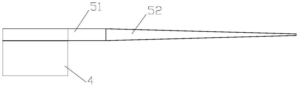
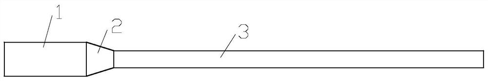
[0033] The optical fiber structure of the embodiment of the present invention is used in an optical fiber scanner as a scanning optical fiber. For the optical fiber structure, see image 3 , Figure 4 As shown, it includes a fixed part 1 and a cantilever part, the fixed part 1 is used to be fixed on the actuator 4 of the fiber optic scanner, and the cantilever part exceeds the actuator to form a fiber cantilever; the cantilever part includes a buffer part 2 and a m...


PUM


Abstract

The invention discloses an optical fiber structure and an optical fiber scanner adopting the optical fiber structure, the optical fiber structure comprises a fixed part and a cantilever part, the fixed part is used for being fixed on an actuator of the optical fiber scanner, and the cantilever part exceeds the actuator to form an optical fiber cantilever; the cantilever part comprises a buffer part and a main cantilever section, the buffer part is located between the main cantilever section and the fixed part, the optical fiber shape of the buffer part and the front and rear optical fibers form a shape difference, and the buffer part comprises one or more buffer sections. The stress borne by the fixed part when the optical fiber cantilever swings can be effectively reduced.

Description

technical field [0001] The invention relates to the field of display technology, in particular to an optical fiber structure and an optical fiber scanner using the optical fiber structure. Background technique [0002] Optical fiber is an important optical waveguide device. Using optical fiber to guide the light emitted by the light source or collecting image information at the end of the optical fiber is two important aspects of optical fiber applications, such as medical endoscope systems and laser projection systems. It is an important breakthrough in the application of optical fiber to realize the vibration scanning of optical fiber by integrating optical fiber with piezoelectric devices with vibration characteristics. So far, many optical fiber scanning systems based on this concept have emerged on the market. At present, optical fiber-based scanning devices are mostly prepared by binding controllable vibration devices and optical fibers, such as piezoelectric ceramic ...

Claims


Application Information

Patent Timeline
Patent Type & Authority Applications(China)
IPC IPC(8): G02B26/10G02B6/46
CPCG02B26/103G02B6/46
Inventor 不公告发明人
Owner CHENGDU IDEALSEE TECH
Why Eureka
Try Eureka