
A multifunctional fuel cell power supply device

A fuel cell and power supply equipment technology, applied in the field of multifunctional fuel cell power supply equipment, can solve problems such as inconvenient use, self-discharge phenomenon, and high oil prices

Active Publication Date: 2022-02-08
SHANDONG JIAOTONG UNIV
View PDF8 Cites 0 Cited by
  • Summary
  • Abstract
  • Description
  • Claims
  • Application Information

AI Technical Summary

Problems solved by technology

[0002] Hydrogen fuel cell is the current global energy shortage and high oil price. It is urgent to find new energy as a substitute for fossil fuel. Fuel cell is considered to be the fourth generation power generation technology after hydropower, thermal power and atomic power generation. It converts oxidant through electrocatalytic reaction It is an efficient, safe, clean and flexible new power generation technology, and the proton exchange membrane fuel cell has high efficiency, high energy density, low reaction temperature, no noise, Due to its obvious advantages such as no pollution, it has broad application prospects in ground power stations, electric vehicles and portable power supplies. However, during the use of traditional hydrogen fuel cells, hydrogen cylinders are generally disposable and need to be Return to the factory to re-inflate, and during use, if the hydrogen cylinder is not removed, there will be self-discharge, which is not convenient to use

Method used


Image

  • A multifunctional fuel cell power supply device
  • A multifunctional fuel cell power supply device
  • A multifunctional fuel cell power supply device

Examples


Embodiment Construction

[0013] In order to make the purpose, technical solutions and advantages of the embodiments of the present invention clearer, the technical solutions in the embodiments of the present invention will be clearly and completely described below in conjunction with the drawings in the embodiments of the present invention. Obviously, the described embodiments It is a part of embodiments of the present invention, but not all embodiments. Based on the embodiments of the present invention, all other embodiments obtained by persons of ordinary skill in the art without creative efforts fall within the protection scope of the present invention.

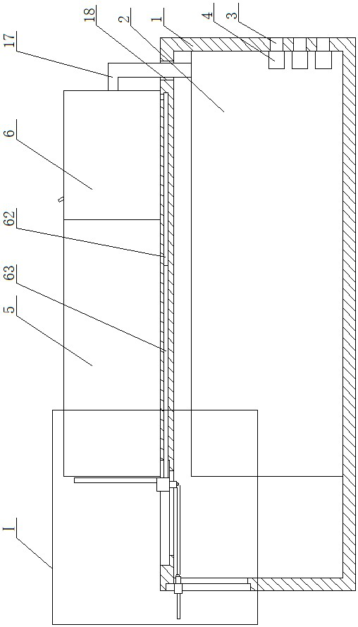
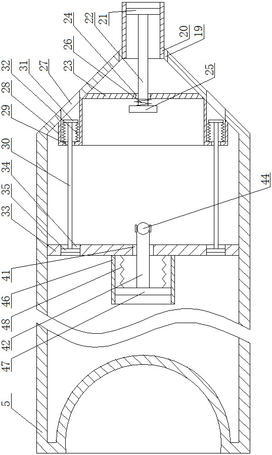
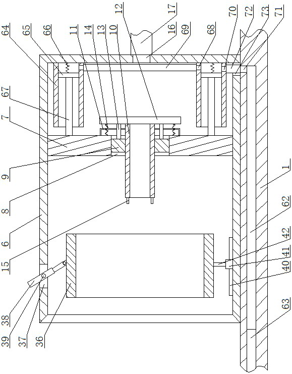
[0014]A multi-functional fuel cell power supply device, as shown in the figure, includes a charging device and an inflating device. The charging device includes a box body 1, and a fuel cell 2 is fixedly installed in the box body 1. There are several outlets on the right side of the box body 1 near the bottom. The first through hole 3, the positio...


PUM


Abstract

A multifunctional fuel cell power supply device, including a charging device and an inflating device, the charging device includes a box body, a fuel cell is placed in the box body, a first through hole is opened on the right side of the box body, and a charging interface is opened at the position corresponding to the first through hole of the fuel cell , there is a hydrogen interface device on the top surface of the box, a hydrogen bottle on the top surface of the box, and a limit device on the left side of the box. The hydrogen interface device includes a first sleeve, and the ninth through hole is opened on the first sleeve, and the ninth through hole There is an elastic telescopic rod inside, the right end of the hydrogen cylinder is a conical surface, a vertical rod is installed on the inner side of the hydrogen cylinder, an annular through hole is opened inside the hydrogen cylinder, and an annular box is arranged in the annular through hole, and the inflation device can effectively inflate the hydrogen cylinder. In the process of use, the invention only needs to manually toggle the elastic telescopic rod to open and close the hydrogen bottle, reducing the self-discharge phenomenon of the fuel cell, and when the hydrogen in the hydrogen bottle is used up, it only needs to be installed on the inflator The device can be used next time after being inflated, and the device can be reused.

Description

technical field [0001] The invention belongs to the field of fuel cell power supply equipment, in particular to a multifunctional fuel cell power supply equipment. Background technique [0002] Hydrogen fuel cell is the current global energy shortage and high oil price. It is urgent to find new energy as a substitute for fossil fuel. Fuel cell is considered to be the fourth generation power generation technology after hydropower, thermal power and atomic power generation. It converts oxidant through electrocatalytic reaction It is an efficient, safe, clean and flexible new power generation technology, and the proton exchange membrane fuel cell has high efficiency, high energy density, low reaction temperature, no noise, Due to its obvious advantages such as no pollution, it has broad application prospects in ground power stations, electric vehicles and portable power supplies. However, during the use of traditional hydrogen fuel cells, hydrogen cylinders are generally dispos...

Claims


Application Information

Patent Timeline
Patent Type & Authority Patents(China)
IPC IPC(8): H01M8/04082
CPCH01M8/04208Y02E60/50
Inventor 仇方圆包乌吉斯古楞褚瑞霞黄万友杨君富文军王金波徐传燕
Owner SHANDONG JIAOTONG UNIV
Learn More