Fault current controller of DC power distribution network and control method

A technology for DC distribution network and fault current, applied in DC network circuit devices, emergency protection circuit devices for limiting overcurrent/overvoltage, electrical components, etc. high cost problem

Active Publication Date: 2018-04-27
INST OF ELECTRICAL ENG CHINESE ACAD OF SCI +1
View PDF7 Cites 5 Cited by
  • Summary
  • Abstract
  • Description
  • Claims
  • Application Information

AI Technical Summary

Problems solved by technology

Therefore, power flow control, voltage compensation and fault current limitation in DC distribution network are important technical issues that must be faced and solved in its future development. Patent CN 201510179145.7 gives the DC power flow controller topology, and patent CN201610638360.3 gives the DC Current limiting device topology, the patent CN201710258530.X provides a DC fault blocking topology, but none of them involve the function reuse of DC equipment
Among the key technologies that need to be solved in the DC distribution network, power flow contr

Method used


Image

  • Fault current controller of DC power distribution network and control method
  • Fault current controller of DC power distribution network and control method
  • Fault current controller of DC power distribution network and control method

Examples


Embodiment 1

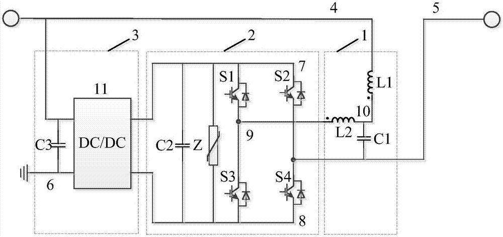
[0042] figure 1 Shown is Example 1 of the present invention. Such as figure 1 As shown, the fault current controller of the present invention includes a filter circuit 1, a series converter circuit 2, and a parallel converter circuit 3; the filter circuit 1 includes a first inductor L1, a first capacitor C1, and a second inductor L2; the The series converter circuit 2 includes a second capacitor C2, a first arrester Z, a first power electronic switching device S1, a second power electronic switching device S2, a third power electronic switching device S3 and a fourth power electronic switching device S4; The parallel converter includes a third capacitor C3 and a first DC / DC circuit 11; the series converter circuit 2 is connected in series between the fourth connection point 4 of the DC power distribution line and the fifth connection point 5 of the DC power distribution line.

[0043]The first lead-out terminal of the first inductor L1, the first lead-out terminal of the thi...

Embodiment 2

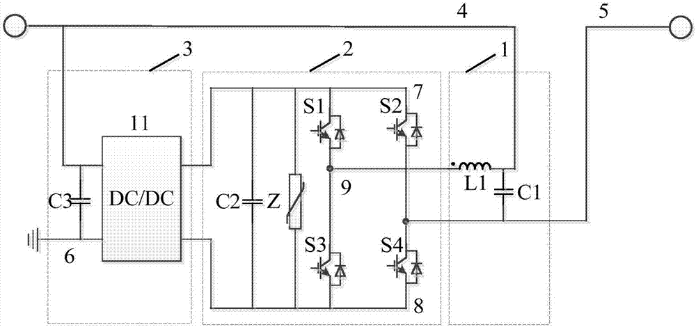
[0054] figure 2 Shown is Example 2 of the present invention. Such as figure 2 As shown, the fault current controller of the present invention includes a filter circuit 1, a series converter circuit 2 and a parallel converter circuit 3; the filter circuit 1 includes a first inductor L1 and a first capacitor C1; the series converter circuit 2 Including the second capacitor C2, the first arrester Z, the first power electronic switching device S1, the second power electronic switching device S2, the third power electronic switching device S3 and the fourth power electronic switching device S4; the parallel converter circuit 3 Including the third capacitor C3 and the first DC / DC circuit 11; the series converter circuit 2 is connected in series between the fourth connection point 4 of the DC power distribution line and the fifth connection point 5 of the DC power distribution line.

[0055] The second lead-out terminal of the first inductance L1, the first lead-out terminal of t...

Embodiment 3

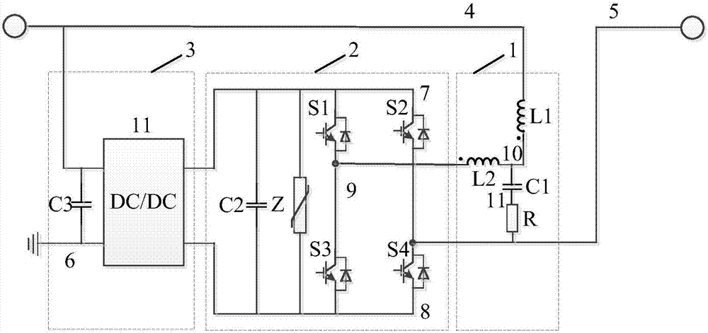
[0059] image 3 Shown is Example 3 of the present invention. Such as image 3 As shown, the fault current controller of the present invention includes a filter loop 1, a series converter loop 2 and a parallel converter loop 3; the filter loop 1 includes a first inductor L1, a first capacitor C1, a second inductor L2 and a first Resistor R; the series converter circuit 2 includes a second capacitor C2, a first arrester Z, a first power electronic switching device S1, a second power electronic switching device S2, a third power electronic switching device S3 and a fourth power electronic switch Device S4; the parallel converter circuit 3 includes a third capacitor C3 and a first DC / DC circuit 11; the series converter circuit 2 is connected in series with the fourth connection point 4 of the DC power distribution line and the fifth connection point of the DC power distribution line Between connection points 5.

[0060] The first lead-out terminal of the first inductor L1, the ...


PUM


Abstract

The invention relates to a fault current controller of a DC power distribution network. The fault current controller comprises a filtering loop, a series converter loop and a parallel converter loop,wherein the filtering loop comprises an LCL filter, the series converter loop comprises a full-bridge circuit, and the parallel converter loop comprises a DC/DC circuit. Under a steady-state condition, the fault current controller can be used for compensating temporary rising and temporary reduction of a voltage of a circuit and pulse; and under a fault condition, the fault current controller canbe used for providing current-limiting inductance and a reverse voltage, voltage adjustment of the DC power distribution network is comprehensively achieved, various functions of fault current limiting and blocking is achieved, and the application efficiency of the fault current controller is improved.

Description

technical field [0001] The invention relates to a fault current controller and a control method of a direct current distribution network, belonging to the technical field of direct current distribution networks. Background technique [0002] Compared with the AC distribution network, the DC distribution network has better performance in terms of transmission capacity, controllability, and power supply quality improvement. It can effectively improve the power supply capacity and power quality, and quickly and independently control active and reactive power. Power, reduce the use of power electronic converters, reduce power loss and operating costs, coordinate the contradiction between large power grids and distributed power, give full play to the value and benefits of distributed energy, and also help enterprises to adopt more energy-saving technology to improve energy efficiency. Therefore, the DC distribution network with reliability, safety, stability and economy has huge...

Claims


Application Information

Patent Timeline
IPC IPC(8): H02J1/00H02H9/02
Inventor 尹靖元吴理心李强柳丹陈亮黄强袁晓冬韦统振
Owner INST OF ELECTRICAL ENG CHINESE ACAD OF SCI
Why Eureka
Try Eureka