
Cable connector protection structure

A technology of cable connectors and protective structures, which is applied in the direction of cable connectors, components of connecting devices, connections, etc., and can solve problems such as cable connector wear, cable exposure, and circuit interruption.

Inactive Publication Date: 2021-03-05
新昌县羽林街道东商机械厂
View PDF0 Cites 2 Cited by
  • Summary
  • Abstract
  • Description
  • Claims
  • Application Information

AI Technical Summary

Problems solved by technology

However, when the outer tape of the cable is rubbed for a long time, the cable will also be exposed, and when the tape is wound unevenly, it is easy to cause the copper wire to be exposed when the cable is pulled, and even cause a short circuit of the cable. In the prior art, it is often used The cable connector replaces the adhesive tape so that accidents can be greatly reduced. With the extensive use of the cable connector, although the occurrence of large-scale accidents has been avoided, the phenomenon of cable connector wear and tear has occurred, resulting in circuit interruption and the like; for this reason, the present invention proposes A protective structure for cable connectors optimizes the structure of traditional cable connectors

Method used


Image

  • Cable connector protection structure
  • Cable connector protection structure
  • Cable connector protection structure

Examples


Embodiment Construction

[0021] The technical solutions in the embodiments of the present invention will be clearly and completely described below. The embodiments of the present invention and all other embodiments obtained by persons of ordinary skill in the art without making creative efforts belong to the protection scope of the present invention.

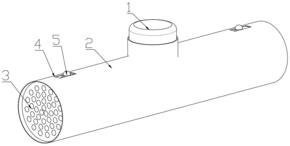
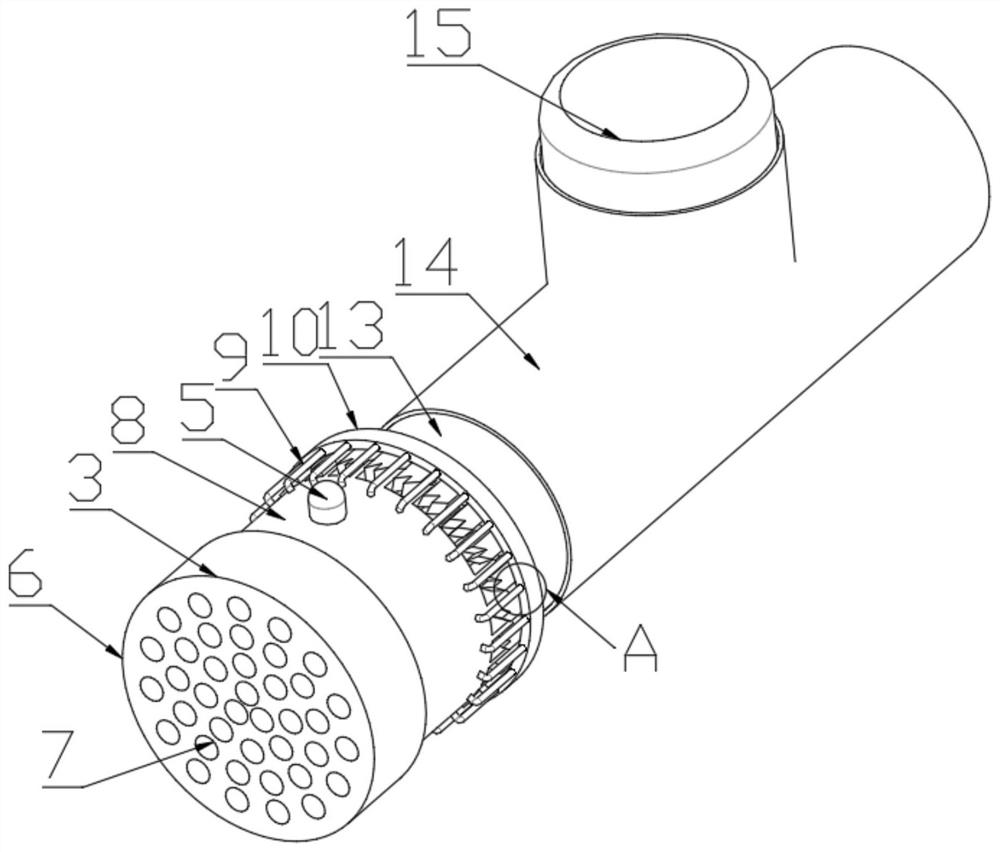
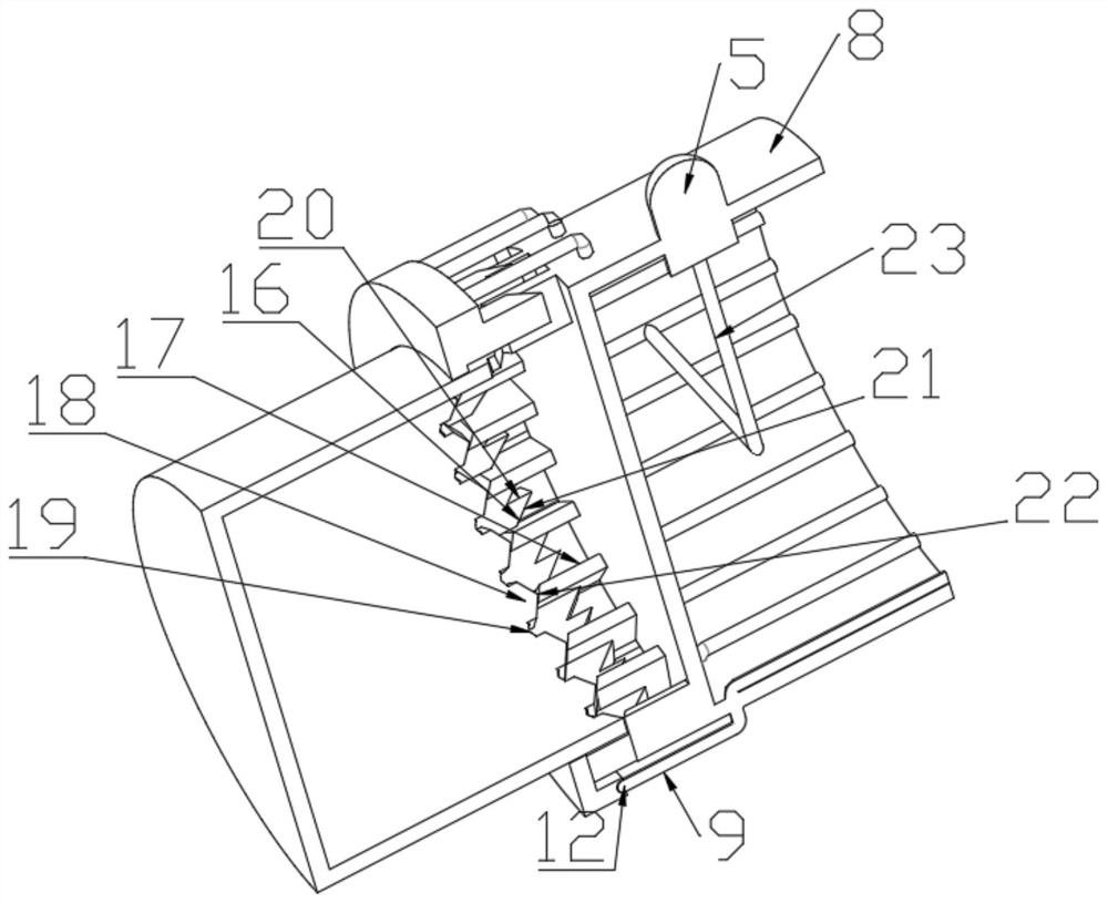
[0022] see Figure 1 to Figure 5 , the present invention provides a technical solution: a protective structure of a cable connector, including a pressure transmission device 1, a housing 2 and an expansion joint 3, the left and right sides of the housing 2 are provided with moving holes 4, the housing 2 is a T-shaped structure, and the moving The hole 4 is a cuboid structure, and the moving hole 4 is provided with an indicator light 5. The indicator light 5 is a cylindrical structure with a hemisphere at the top. A sealing tube 14 is installed on the pressure transmission device 1. The sealing tube 14 is a T-shaped structure. 14 top is provided with pr...


PUM


Abstract

The invention relates to the field of cable connectors, in particular to a cable connector protection structure which comprises a pressure transmission device, a shell and a telescopic connector, moving holes are formed in the left side and the right side of the shell, indicator lamps are arranged in the moving holes, a sealing pipe is installed on the pressure transmission device, a pressing block is arranged at the top end of the sealing pipe, and a telescopic block is arranged on the side face of the sealing pipe. The top of the telescopic joint is provided with a connecting plug, the frontend face of the connecting plug is provided with a plug hole, the rear end face of the connecting plug is provided with a connecting shaft, twenty-five conduits are installed on the connecting shaftin a circumferential array mode, the tail ends of the conduits are provided with a connecting table,two parallel pipes are symmetrically mounted on the left side and the right side of the bottom of each indicator lamps,a fixed table is arranged outside the connecting table, and twenty-five connecting holes are formed in the fixed table in a circumferential array mode; and the protection structureof the cable connector has the beneficial effects that the protection structure of the cable connector optimizes the structure of a traditional cable connector, so that the cable connector has a protection function.

Description

technical field [0001] The invention relates to the field of cable connectors, in particular to a protective structure for cable connectors. Background technique [0002] Power equipment mainly includes power generation equipment and power supply equipment. Power generation equipment is mainly power plant boilers, steam turbines, gas turbines, water turbines, generators, transformers, etc. Power supply equipment is mainly transmission lines of various voltage levels, transformers, contactors, etc. Connectors, etc., the joints in the middle of the cortical cables are usually sealed with insulating tape. However, when the outer tape of the cable is rubbed for a long time, the cable will also be exposed, and when the tape is wound unevenly, it is easy to cause the copper wire to be exposed when the cable is pulled, and even cause a short circuit of the cable. In the prior art, it is often used The cable connector replaces the adhesive tape so that accidents can be greatly redu...

Claims


Application Information

Patent Timeline
IPC IPC(8): H02G15/18H01R13/629H01R13/502H01R13/639
CPCH01R13/502H01R13/629H01R13/639H02G15/18
Inventor 钱珅东
Owner 新昌县羽林街道东商机械厂
Learn More