
Single-phase motor

A technology for single-phase motors and shells, which is applied in the direction of electromechanical devices, electrical components, circuit devices, etc., can solve the problems of users' economic losses, potential safety hazards, and loud noises of motors, and achieve easy installation and disassembly, ensure normal operation, and improve The effect of thermal performance

Active Publication Date: 2021-03-05
ZHEJIANG CHUANGMEI ELECTROMOTOR
View PDF5 Cites 0 Cited by
  • Summary
  • Abstract
  • Description
  • Claims
  • Application Information

AI Technical Summary

Problems solved by technology

[0003] In the prior art, there is usually a problem of high noise during the operation of single-phase motors. The size of the noise will vary depending on the structure and material of the motor cover cavity. The common solution is to install noise-absorbing cotton to reduce noise. However, during the use of ultra-high-speed single-phase motors, due to the substantial increase in rotor speed, there is currently no suitable technology to optimize this type of motor, resulting in the following problems in the operation of existing ultra-high-speed motors:
[0004] 1. The motor will generate a lot of noise, and ordinary noise-absorbing cotton cannot achieve a good noise reduction effect. In addition, the ultra-high-speed operation of the rotor will also bring strong vibration, and long-term vibration will loosen the connection between parts , causing potential safety hazards, which is not conducive to safe production;
[0005] 2. Existing single-phase motors usually use a junction box to connect to an external power supply, but the traditional junction box does not have the function of alarming. During the operation of an ultra-high-speed motor, due to excessive voltage, the motor will be overloaded. If it is discovered in time, it will easily cause damage to the motor, cause economic losses to the user, and seriously cause casualties

Method used


Image

  • Single-phase motor
  • Single-phase motor
  • Single-phase motor

Examples


Embodiment Construction

[0036] The technical solutions in the embodiments of the present invention will be clearly and completely described below with reference to the accompanying drawings in the embodiments of the present invention. Obviously, the described embodiments are only a part of the embodiments of the present invention, but not all of the embodiments. Based on the embodiments of the present invention, all other embodiments obtained by those of ordinary skill in the art without creative efforts shall fall within the protection scope of the present invention.

[0037] In the description of the present invention, it should be understood that the terms "center", "longitudinal", "lateral", "length", "width", "thickness", "top", "bottom", "front", " Rear", "Left", "Right", "Straight", "Horizontal", "Top", "Bottom", "Inner", "Outer", "Clockwise", "Counterclockwise" etc. The positional relationship is based on the orientation or positional relationship shown in the accompanying drawings, which is ...


PUM


Abstract

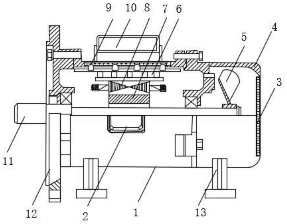
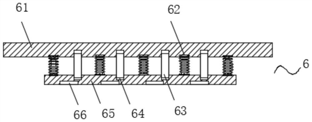
The invention discloses a single-phase motor which comprises a shell, a base is fixedly installed at the lower end of the shell, a front end cover is fixedly installed at the front end of the shell, an output shaft is rotatably installed in the middle of the front end cover, one end of the output shaft penetrates through the front end cover and extends into the shell, and a rear end cover is fixedly installed at the rear end of the shell. A junction box is fixedly installed in the middle of the upper surface of the shell, a capacitor is arranged at the position, close to the junction box, of the upper surface of the shell, a rotor is fixedly installed at the end, extending into the shell, of the output shaft, and a stator is arranged in the shell. By arranging the noise reduction and shockabsorption device, a shock absorption effect is achieved, the problems that connection between parts is loosened due to long-time shock, potential safety hazards are caused and safety is not facilitated can be avoided, noise reduction cotton and noise reduction holes are formed in the noise reduction plate, noise can be well eliminated, and the noise reduction effect of the motor is improved.

Description

technical field [0001] The invention relates to the technical field of motors, in particular to a single-phase motor. Background technique [0002] Single-phase motor refers to an asynchronous motor that is powered by 220V AC single-phase power supply. Because 220V power supply is very convenient and economical, and household electricity is also 220V, so single-phase motors are not only used in large quantities in production, but also It is closely related to people's daily life, especially with the improvement of people's living standards, the amount of single-phase motors in household appliances is also increasing. The working principle of single-phase motors is that when single-phase sinusoidal current passes through the stator winding When the motor generates an alternating magnetic field, the strength and direction of this magnetic field change sinusoidally with time. This alternating pulsating magnetic field can be decomposed into two rotating magnetic fields with the ...

Claims


Application Information

Patent Timeline
Patent Type & Authority Applications(China)
IPC IPC(8): H02K5/24H02K5/18H02K9/06H02K5/22H02K5/10H02H3/04H02H7/085
CPCH02H3/04H02H7/085H02K5/10H02K5/18H02K5/225H02K5/24H02K9/06
Inventor 金可友
Owner ZHEJIANG CHUANGMEI ELECTROMOTOR
Learn More